3D scanner measurement system for SUS plate
Product Features
Measures the width and height of the inspected object using a 3D scanner laser.
Although the thickness of the object to be inspected is 0.1 mm, since a high-precision 3D laser scanner is used, the Z-axis resolution is 4.4-25.9 μm.
Errors such as two SUS plates overlapping can also be detected.
It is also possible to inspect SUS plates placed upside down.
The test results are displayed on the monitor attached to the machine and checked by an inspector.
-
 Only one
-
 Hardware
-
 Software
What is a 3D laser scanner?
A 3D laser scanner uses a laser to measure the distance of an object and can perform highly accurate and detailed measurements.
3D printers and 3D scanners are often thought of as the same thing, but 3D printers read data and create things, and 3D scanners read things and convert them into data.
Although they are thought to be similar, this is a device that can do the exact opposite.
This time, we will use it to read the SUS board, convert it to data, and read the dimensions.
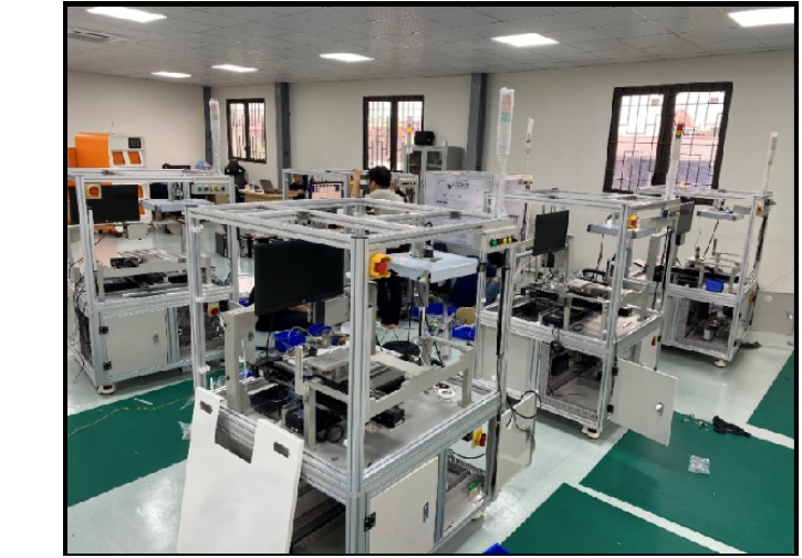
Features 3D INSPECTION MACHINE
Features
- Ability:
- PCB putted on moving jig.
- One inspection speed:
- 1 seconds / PCB
-
3D head scanner:
- X Resolution: 39.1 – 60.0 µm.
- Z resolution: 4.4 – 25.9 µm
- Z repeatability: 1 µm
-
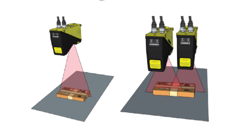
Use one or two 3D laser scanners depending on the size of the SUS board. It is also possible to handle large SUS plates.
This will inspect the thickness of parts, missing parts, and whether parts are in the wrong position.
By placing the SUS board on the rail, it will automatically flow and when it enters the inspection area.
The test will be performed automatically and the test results will be displayed on the monitor.
How to introduce
-
STEP1
Please contact us by phone or E-mail.

-
STEP2
Evaluation of cameras, lenses, and lighting
Although it can be used with commercially available products, we also individually propose products that suit your company.
We also send CDs to those who cannot download. (Japan only)
Sample test:We accept sample test for free.
-
STEP3
Introduction
Technical blog
-
2021.06.21
Camera technique in Pattern matching visual inspection software EI710
-
2021.06.21
How to use lighting in Pattern matching visual inspection software EI710
-
2021.06.21
How to use the mirror in Pattern matching visual inspection software EI710
-
2021.06.21
Multiple frame operation function in Pattern matching visual inspection software EI710
-
2021.06.18
Presence / absence inspection of specified color: Concept of color judgment allowable range and tips for setting
-
2021.06.18
3 types of trigger modes in Pattern matching visual inspection software EI710