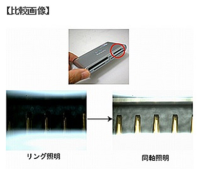
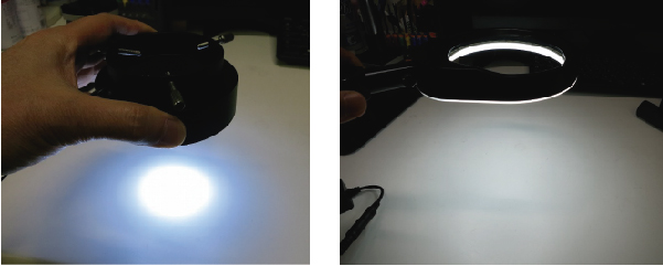
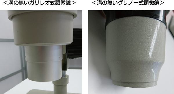
Coaxial light is fundamentally used on “flat” surfaces with “gloss.” The limits of gloss and images for various applications have been verified.
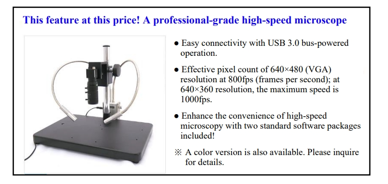
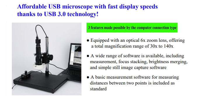
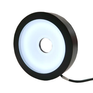
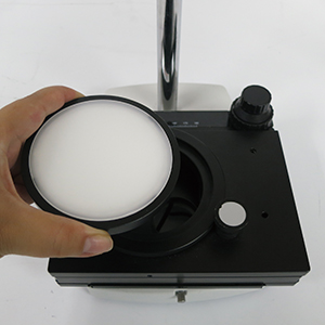
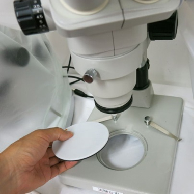
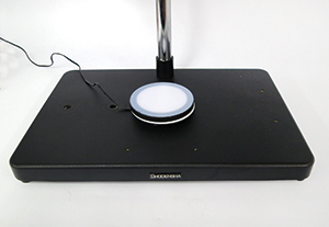
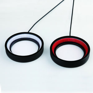
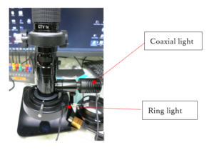
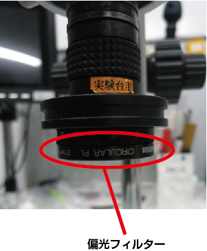
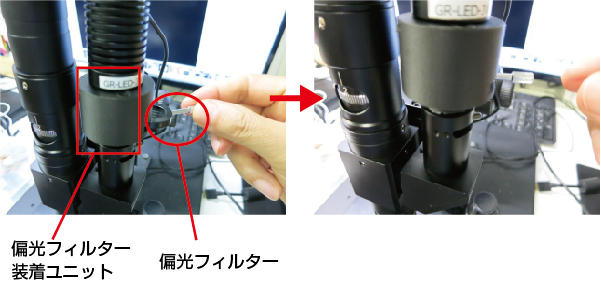
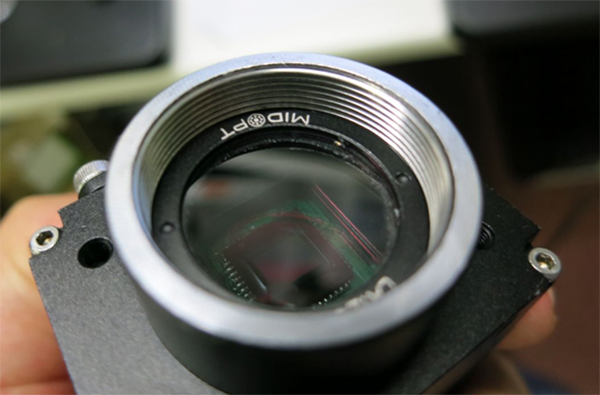
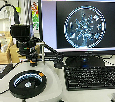
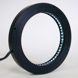
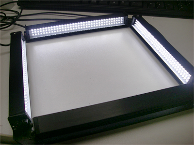
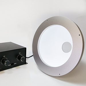
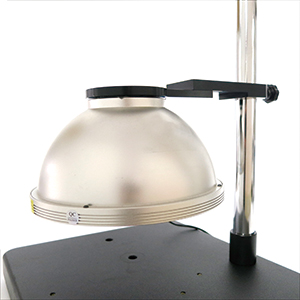
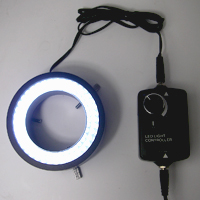
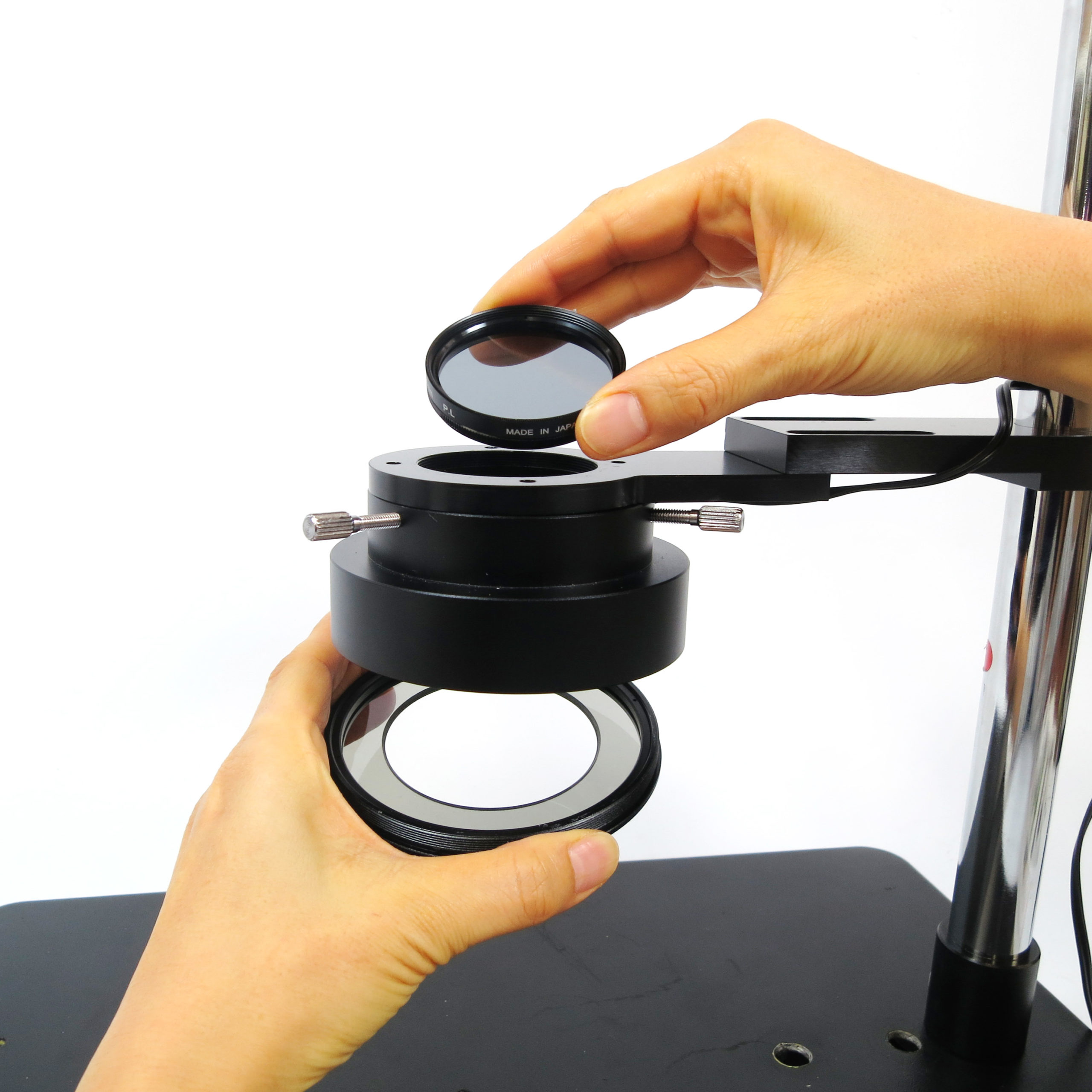
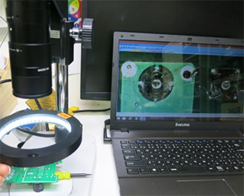
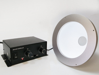
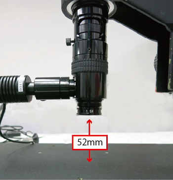
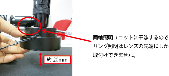
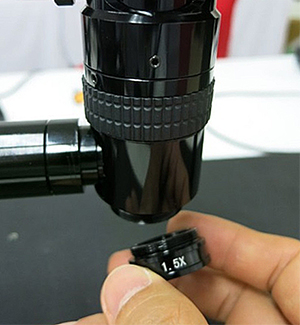
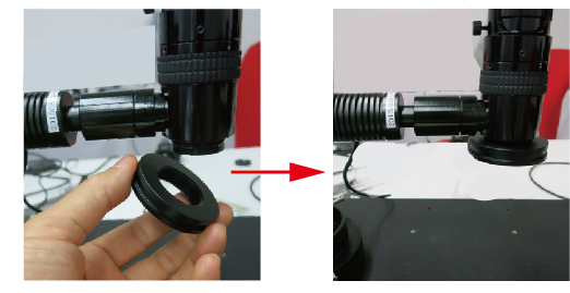
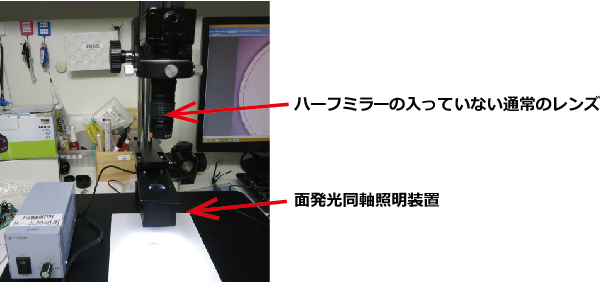
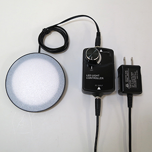
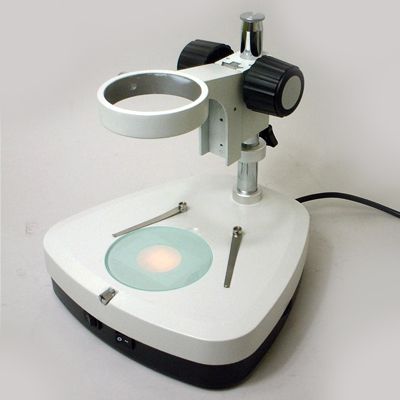
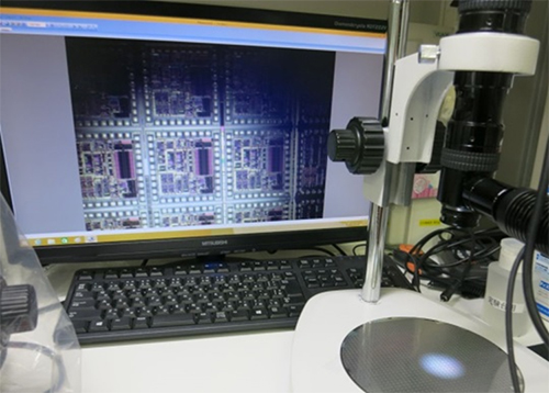
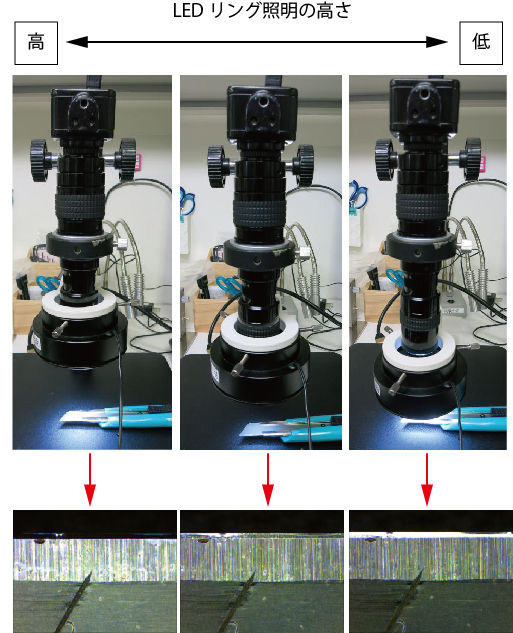
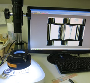
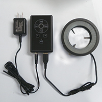
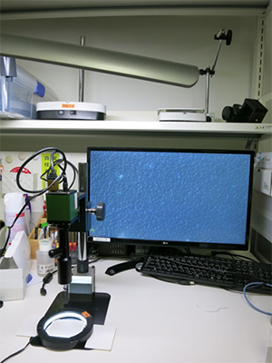
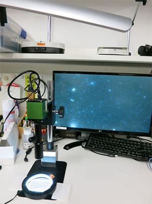
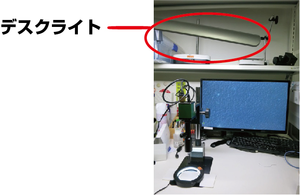
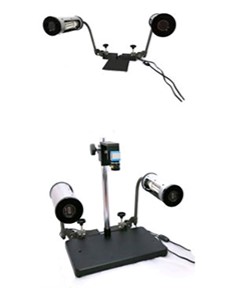
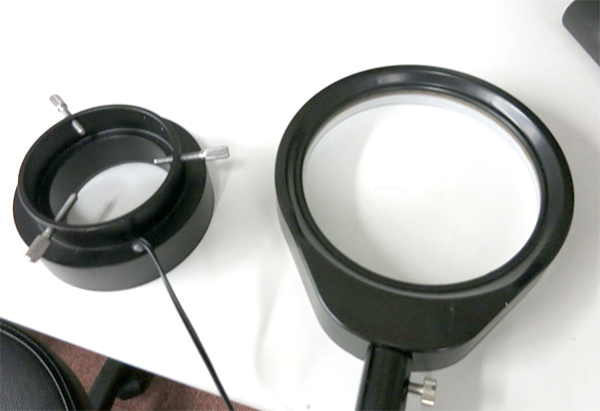
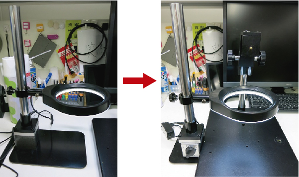
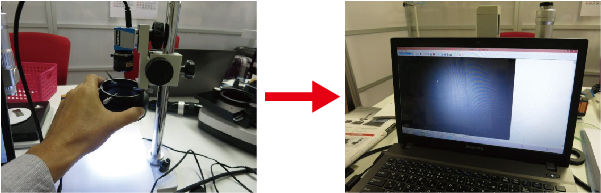
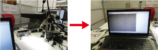
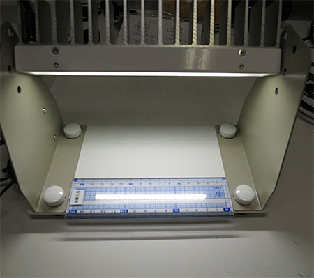
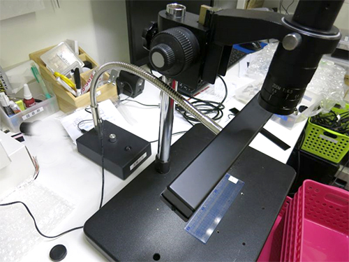
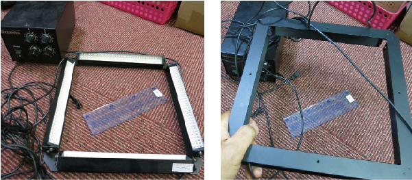
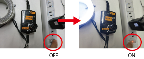
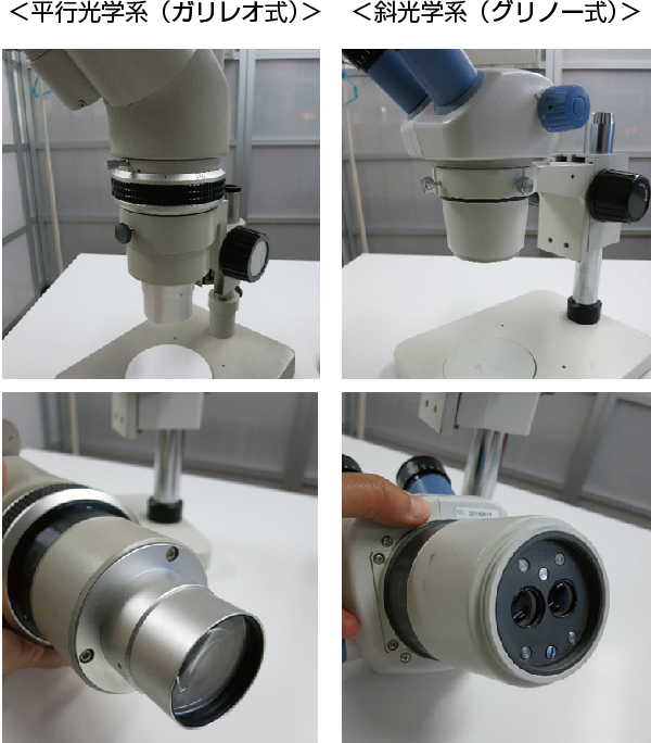
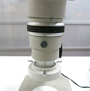
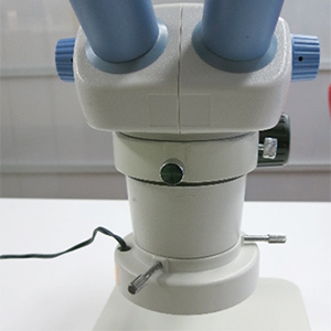
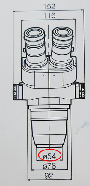
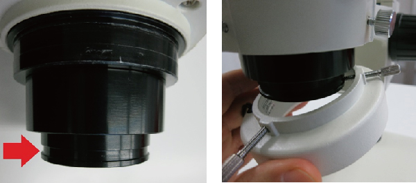
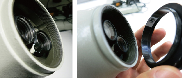
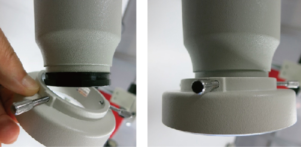
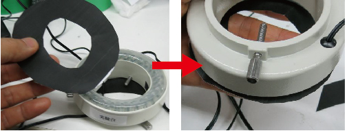
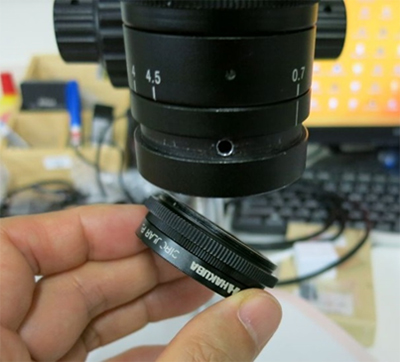
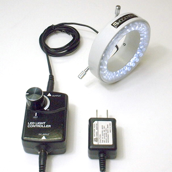
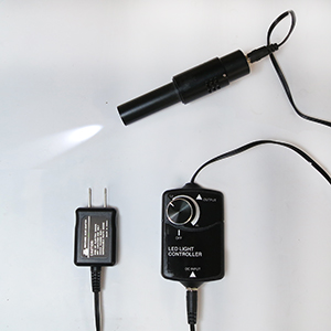
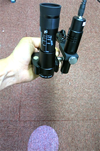
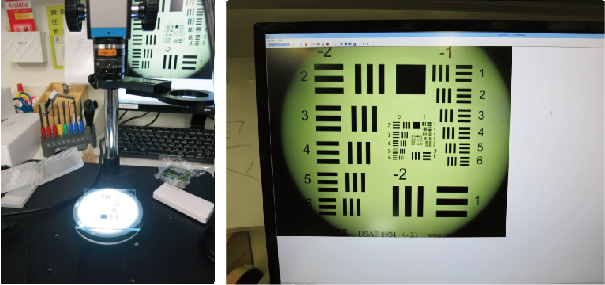
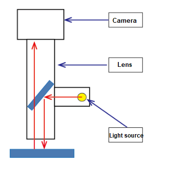
In this instance, we conducted imaging using a microscope that allows switching between “coaxial light” and “ring light.”
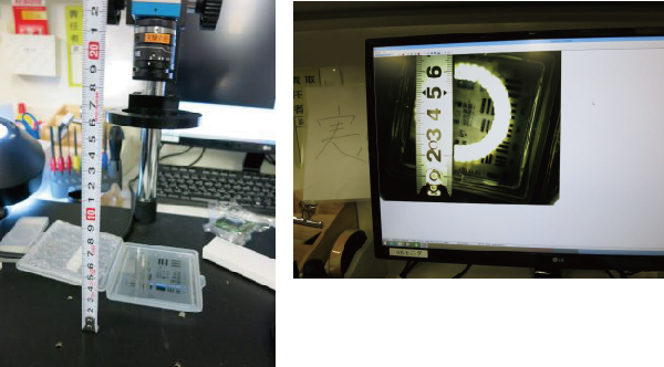
(1) Subjects (regarding gloss)
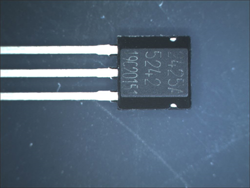
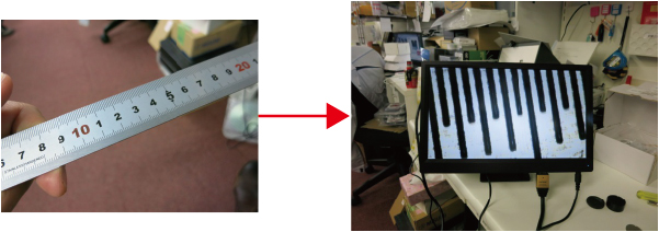
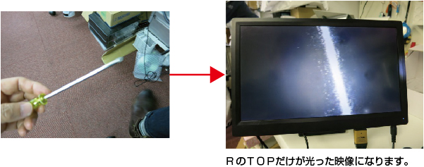
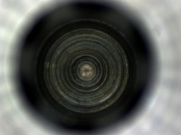
Objects such as plated metals and silicon wafers, which are close to a “mirror finish”, can be observed accurately.
|
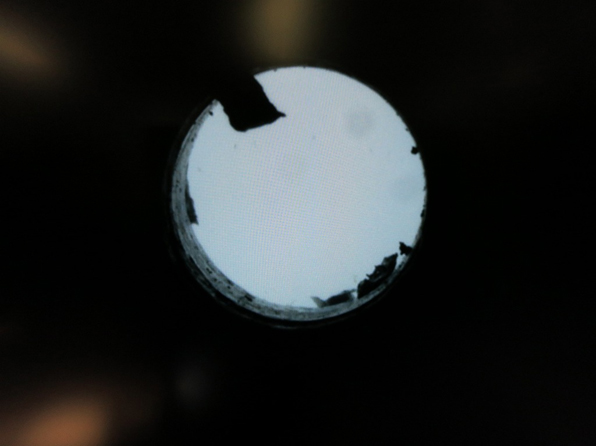
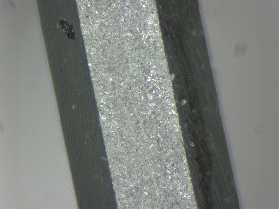
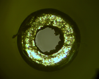
<Observation of silicon wafer using coaxial light>

|
<Observation of silicon wafer using coaxial light>

|
* Objects with surfaces close to a mirror finish will likely exhibit the effects of coaxial light more prominently.
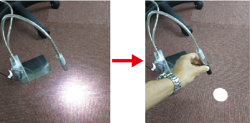
So, at what level of gloss can we differentiate usage?
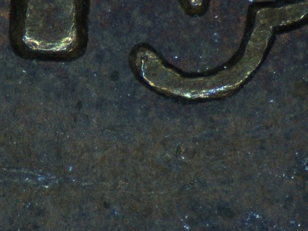
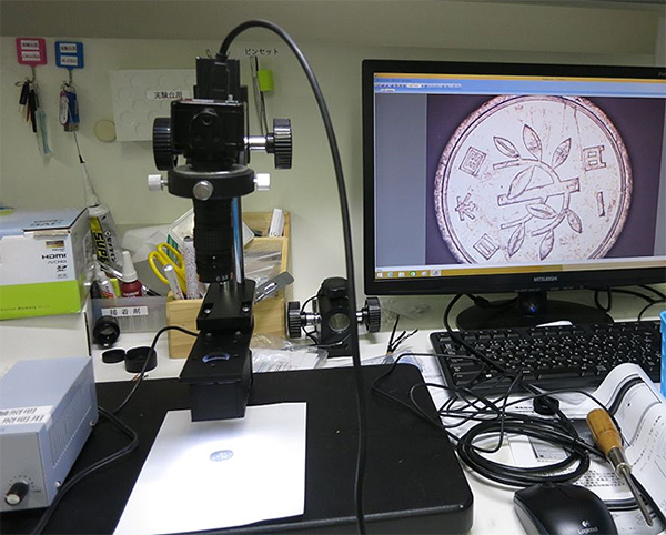
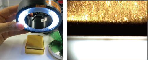
As a general guideline, a comparison can be made between a worn 10-yen coin and a new 10-yen coin.
・10-yen coin
A worn 10-yen coin is best suited for “ring light.”
|
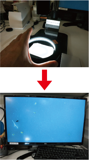
<Observation using ring light>
|
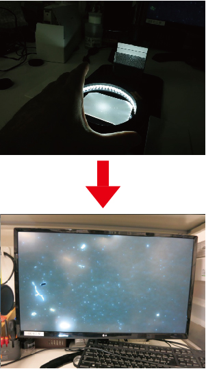
<Observation using coaxial light>

|
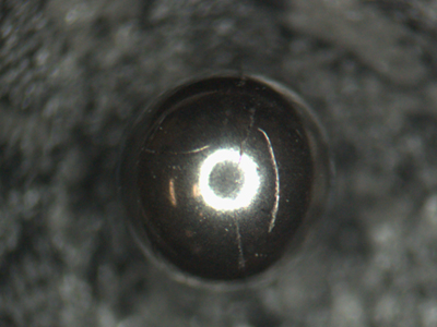
However, if it is a new 10-yen coin, coaxial light is more suitable.
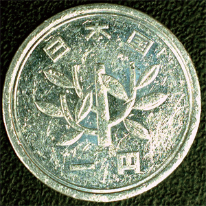
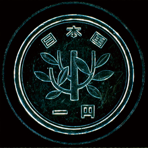
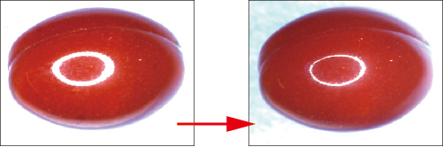
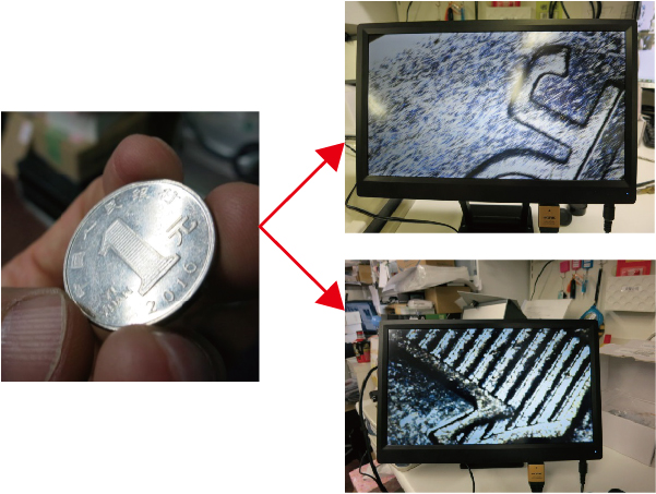
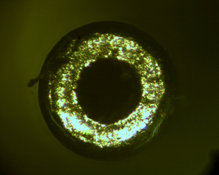
・1-yen coin
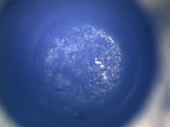
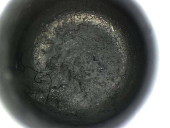
A worn 1-yen coin is suitable for both “coaxial light” and “ring light”.
|
<Observation using coaxial light>

|
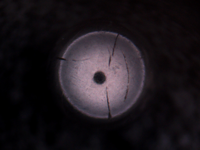
<Observation using ring light>
|
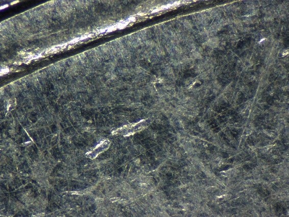
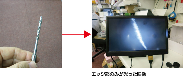
* Both can be used, but coaxial light is more effective for surfaces with pronounced irregularities.
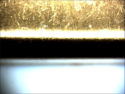
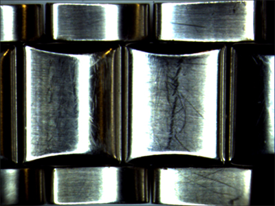
For detecting scratches, coaxial light is preferable.
(2) Subjects (regarding color)
Coaxial light is significantly influenced by differences in reflectance rather than color.
Even black surfaces can utilize coaxial light if they possess gloss.
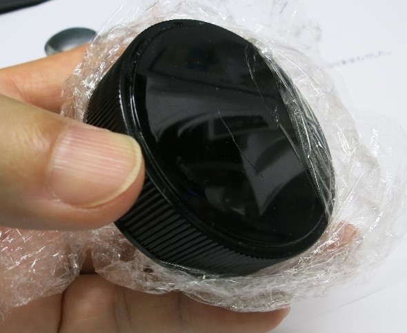
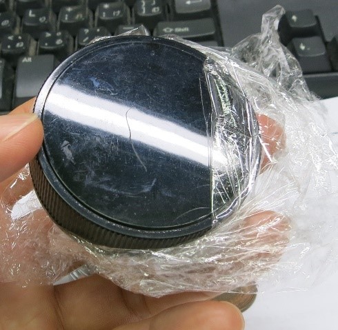
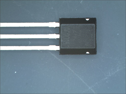
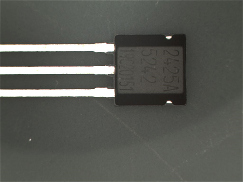
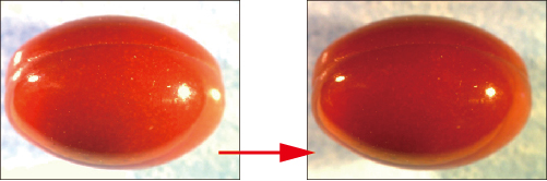
・Black resin
This is a glossy black resin that reflects light to the extent that the fluorescent light directed at the ceiling is visible.
|
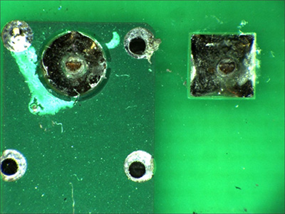
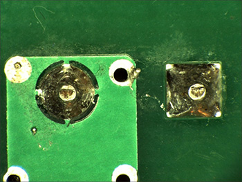
<Observation using coaxial light>
|
<Observation using ring light>
|
* Both can be used, but coaxial light cannot reproduce colors. However, it does clearly highlight surface irregularities.
A characteristic of coaxial light is that reflectance has a greater impact on the image than color.
Even with significant color differences, it is not suitable for materials with uniform reflectance (diffuse reflectors).
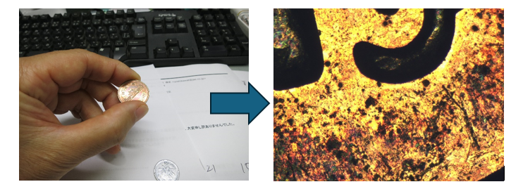
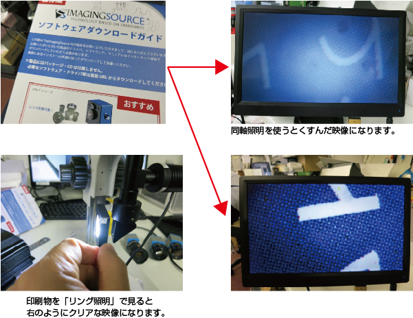
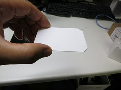
・Printed materials
|
<Observation using ring light>

|
<Observation using coaxial light>
|
* If the variation in reflectance is consistent, using coaxial light will result in a flat image.
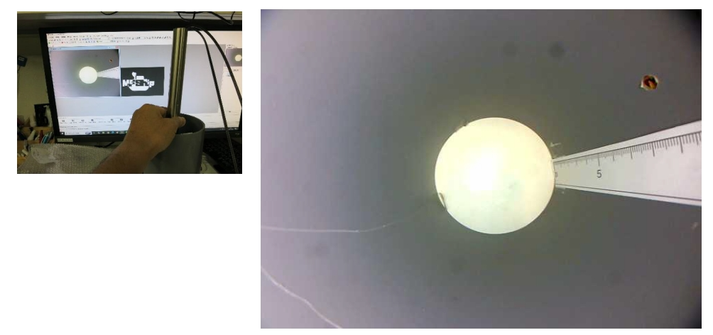
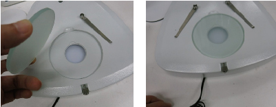
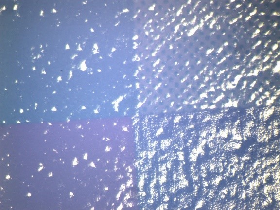
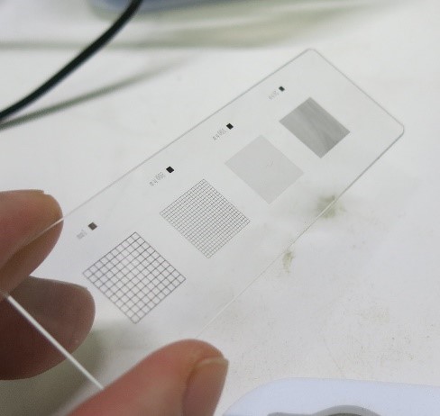
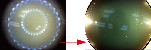
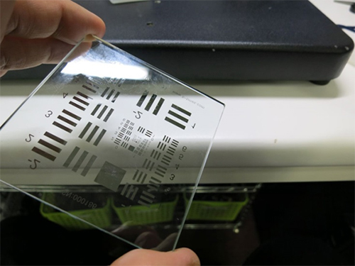
(3) Subjects (regarding transparent objects)
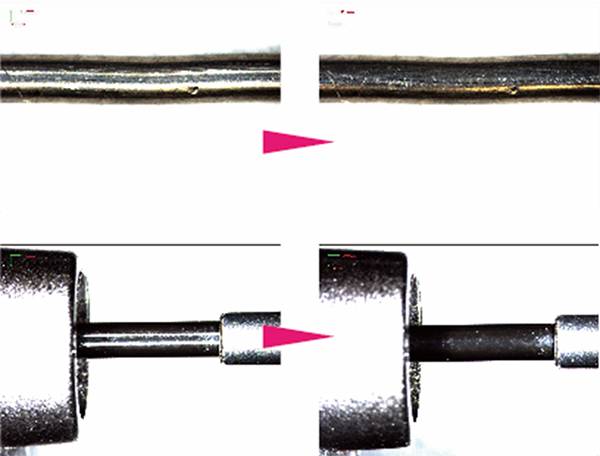
Transparent objects such as glass can be effectively illuminated using coaxial light, depending on the application.
It may be possible to observe the presence of surface coatings or fingerprints (oils) on the glass, provided there are variations in reflectance.
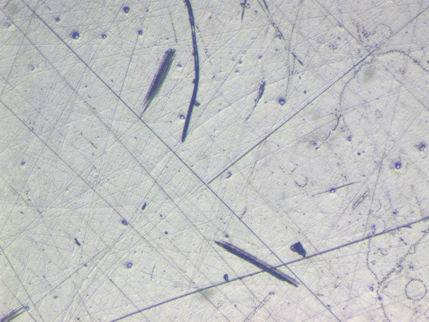
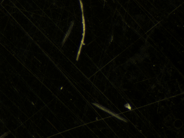
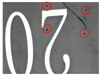
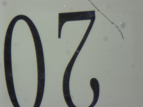
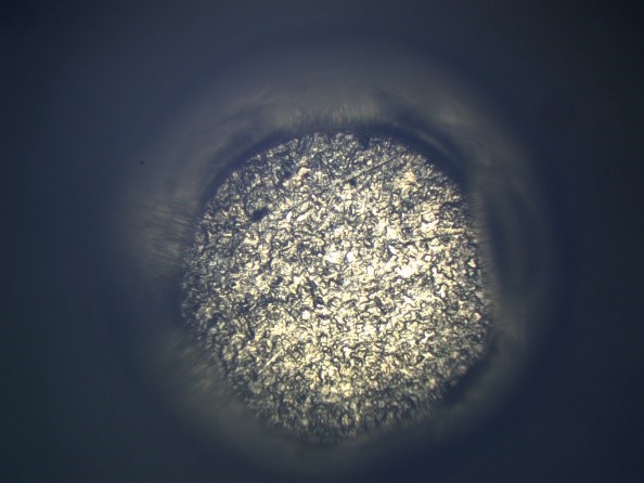
Observe fingerprints (oils) on the surface of the specimen slide.
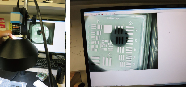
|
<Observation using coaxial light>
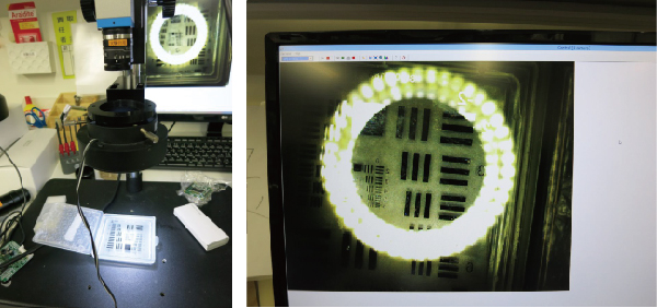
|
<Observation using ring light>
|
* Fingerprints can be observed using coaxial light, but they are not visible at all with ring light.
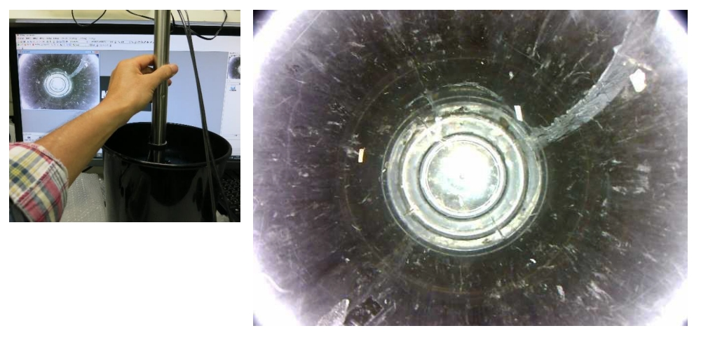
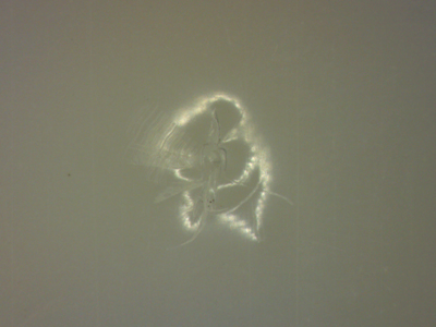
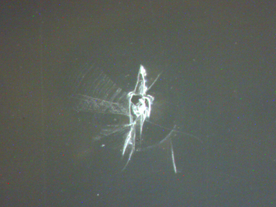
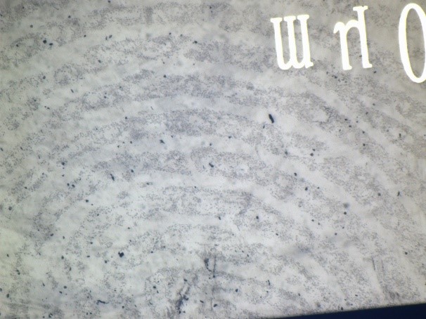
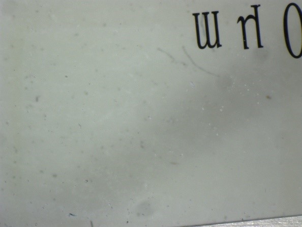
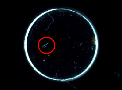
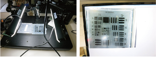
Additionally, dust and foreign particles are easier to observe with coaxial light.
|
<Observation using coaxial light>
|
<Observation using ring light>
|
We also examined the cross-section of the specimen slide.
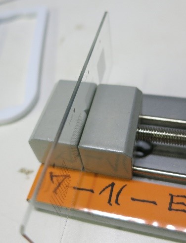
|
<Observation using coaxial light>
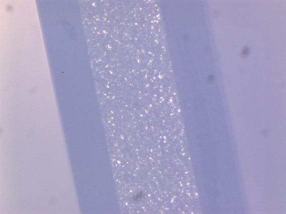
|
<Observation using ring light>
|
* In the case of glass, the observation can vary significantly depending on the polishing condition; however, for specimen slides, it appears that ring light is easier for observation.
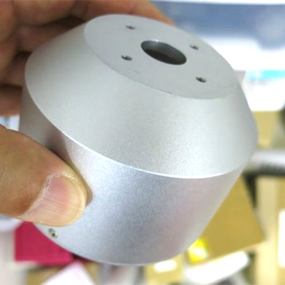


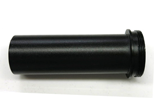

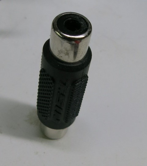
![[Custom-made] Cylinder side inspection device](https://www.shodensha.com.vn/wp-content/uploads/2024/10/machine01.jpg)