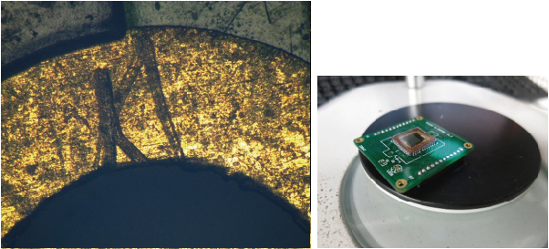
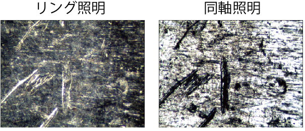
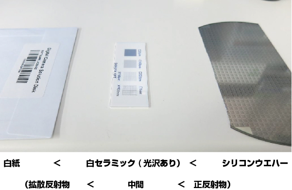
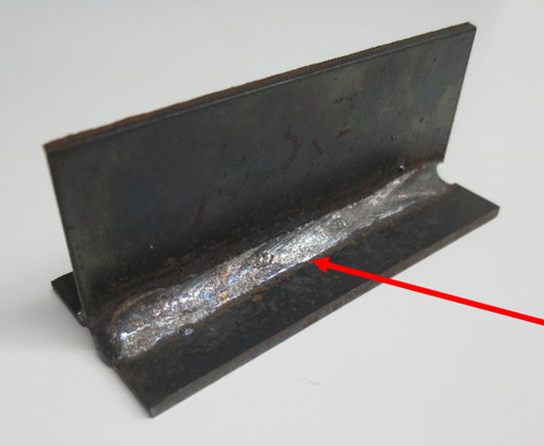
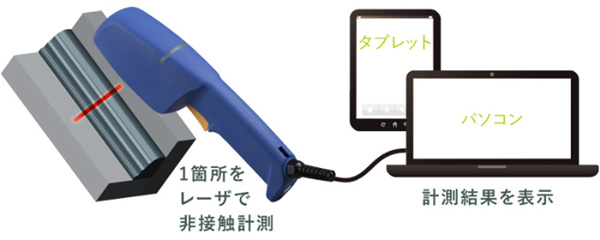
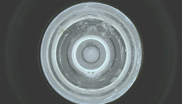
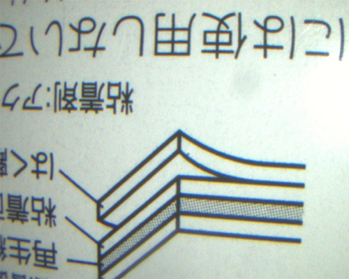
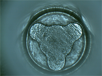
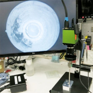
Solder joints contain various curves (R) and also generate reflections, making them difficult to observe with a camera.
We recommend the following three methods for optimal observation:
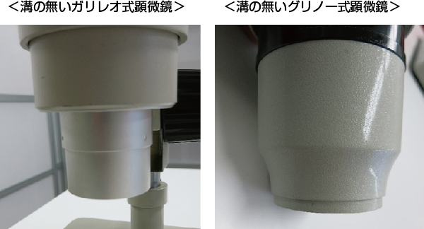
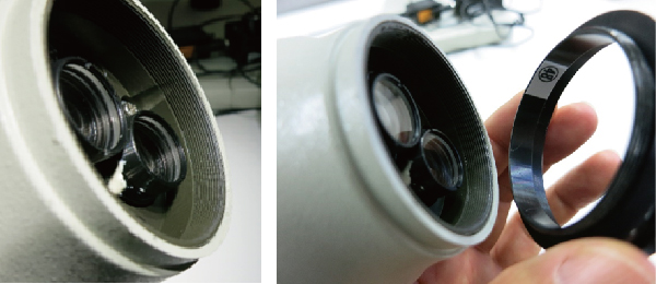
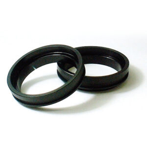
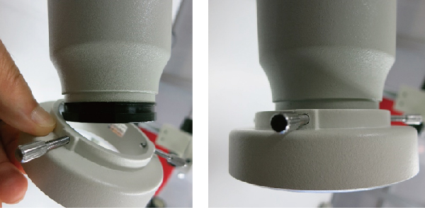
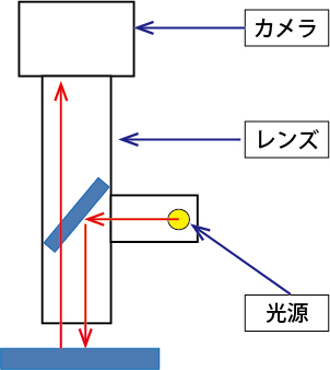
(1) Polarizing filter
(2) Low-angle LED light
(3) HDR (High Dynamic Range) function of high-definition cameras
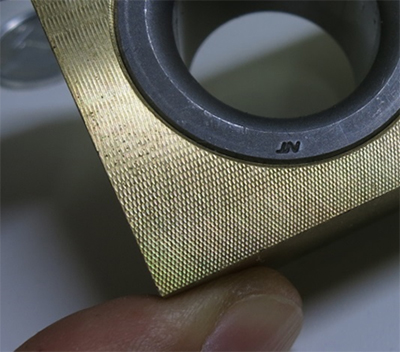
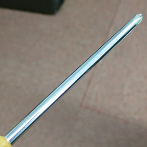
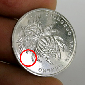
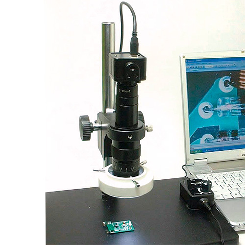
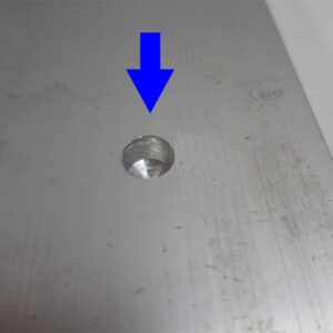
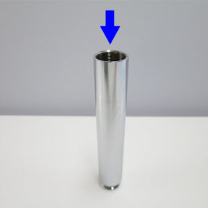
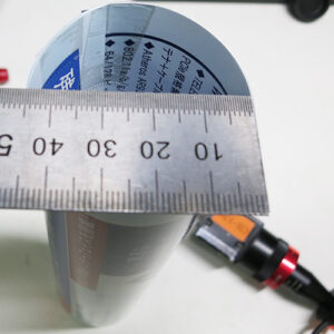
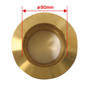
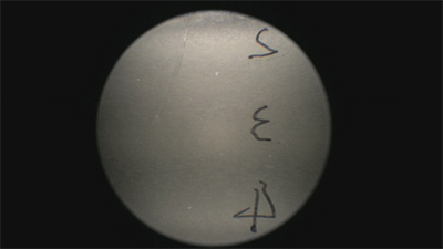
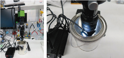
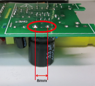
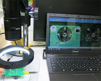
This time, we observed the solder joints on the leads of an 8mm pitch electrolytic capacitor (discrete component).
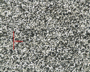
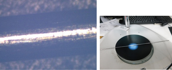
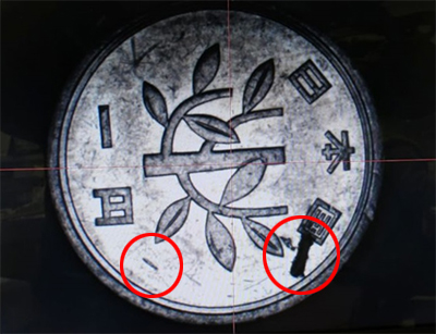
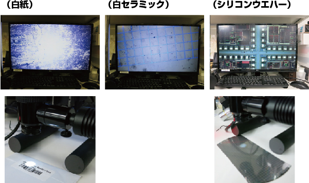
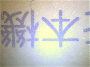
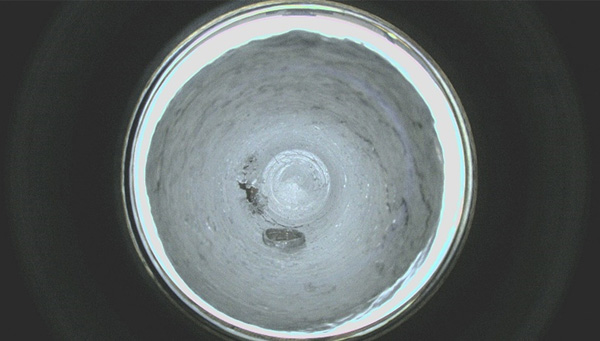
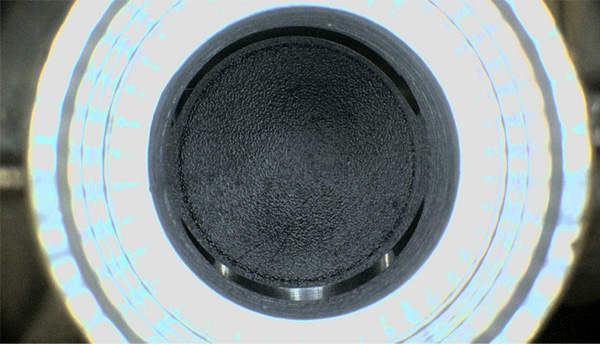
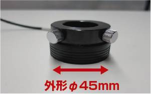
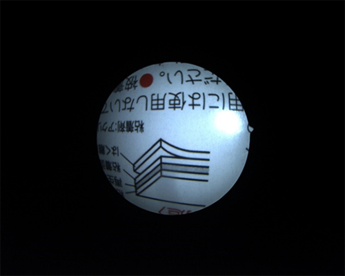
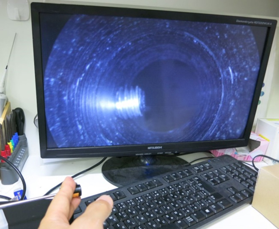
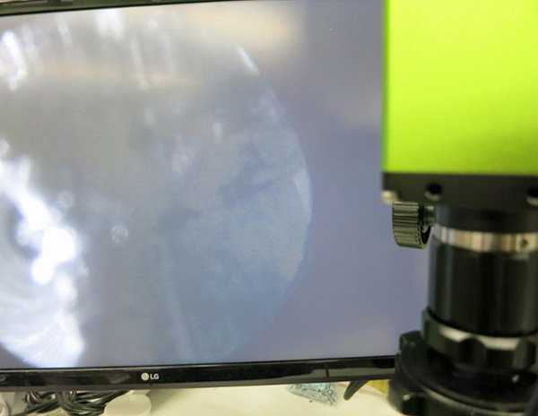
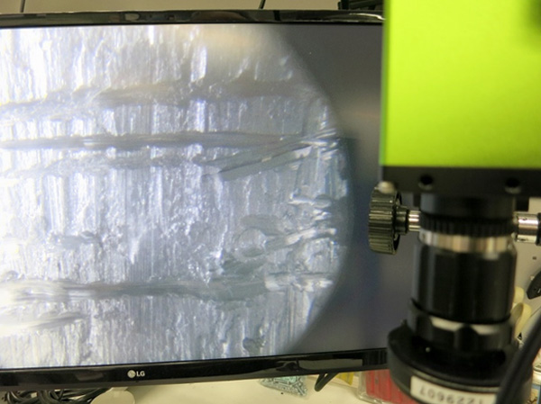
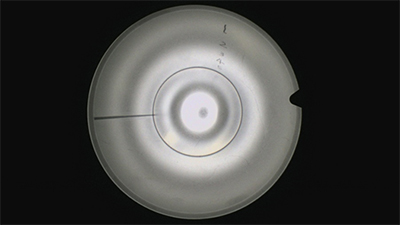
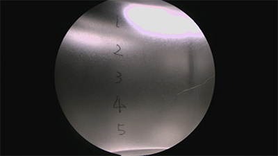
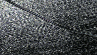
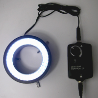
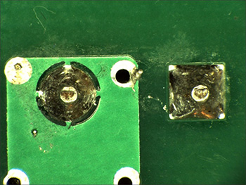
■ Standard ring light |
|
|
High-brightness 80-LED white ring light GR80-N2 |
 |
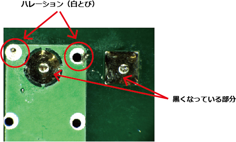
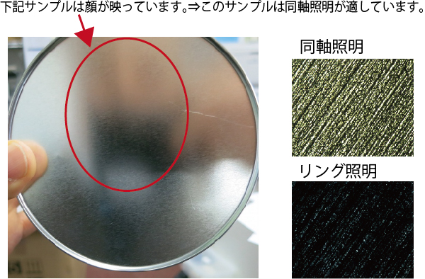
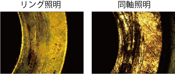
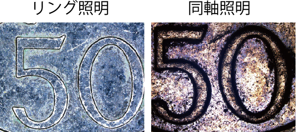
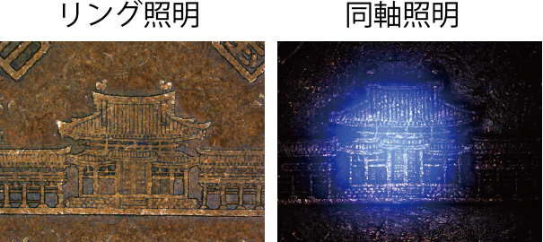
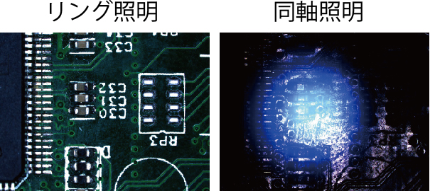
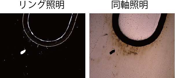
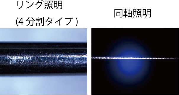
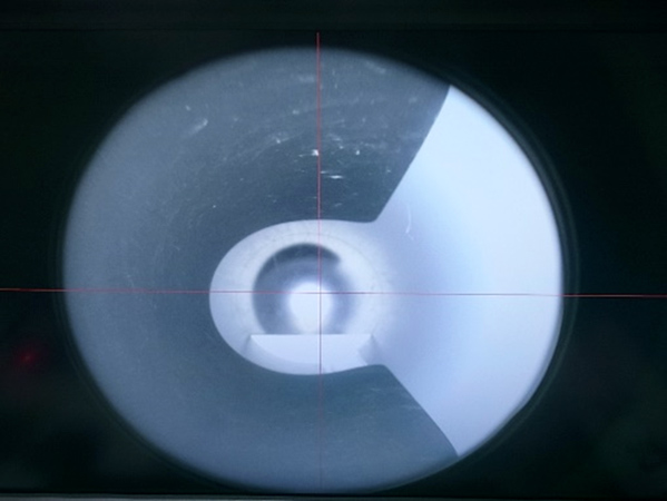
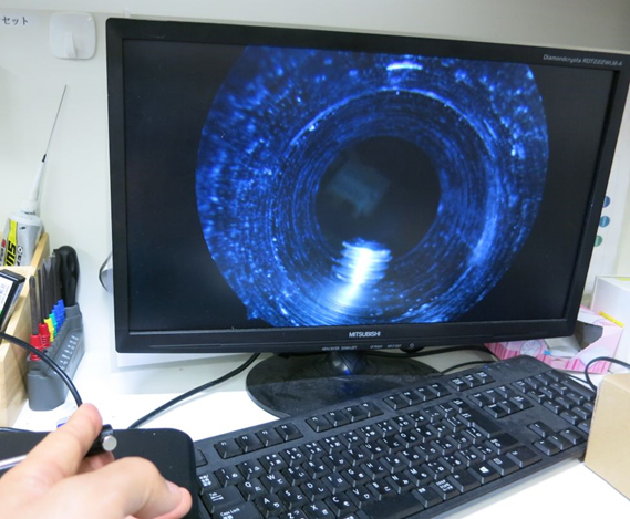
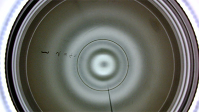
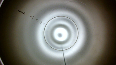
Even with the same solder joint, the angle of the light can cause it to appear blackened or result in halation (white-out).
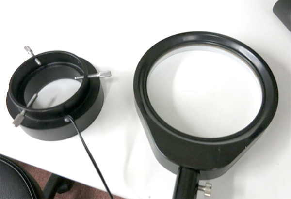
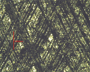
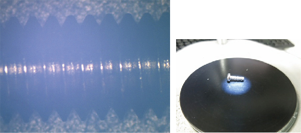
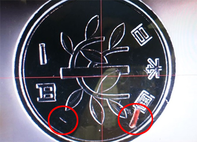
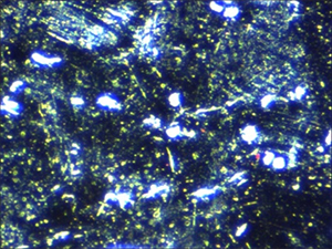
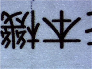
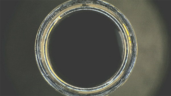
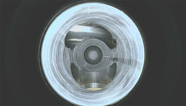
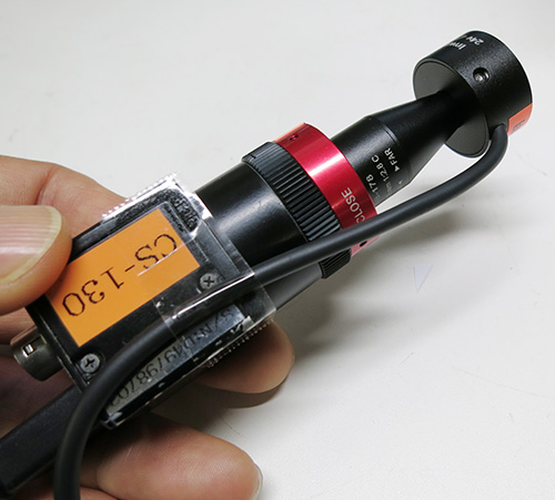
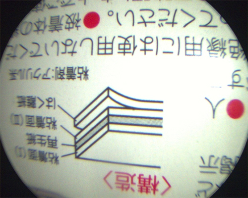
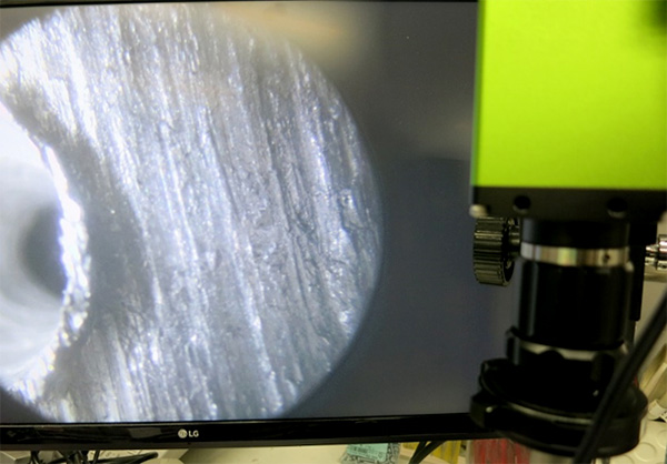
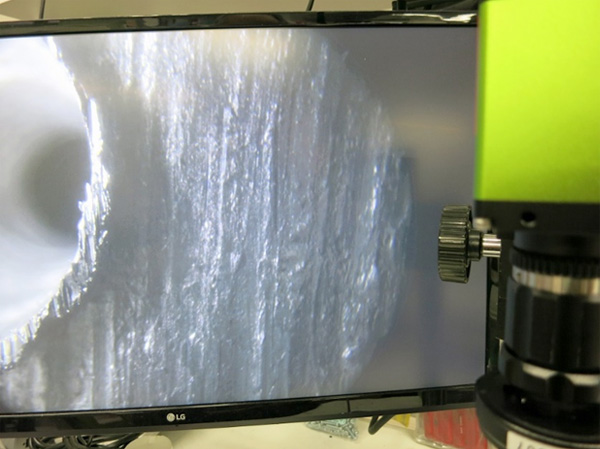
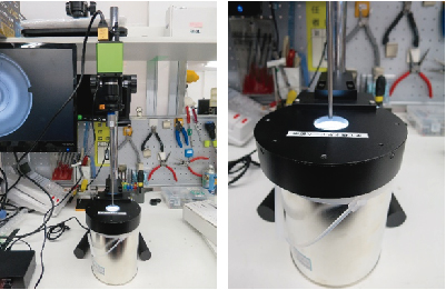
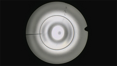
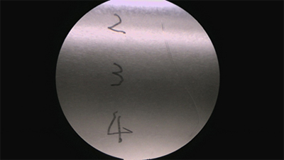
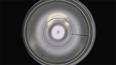
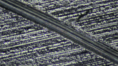
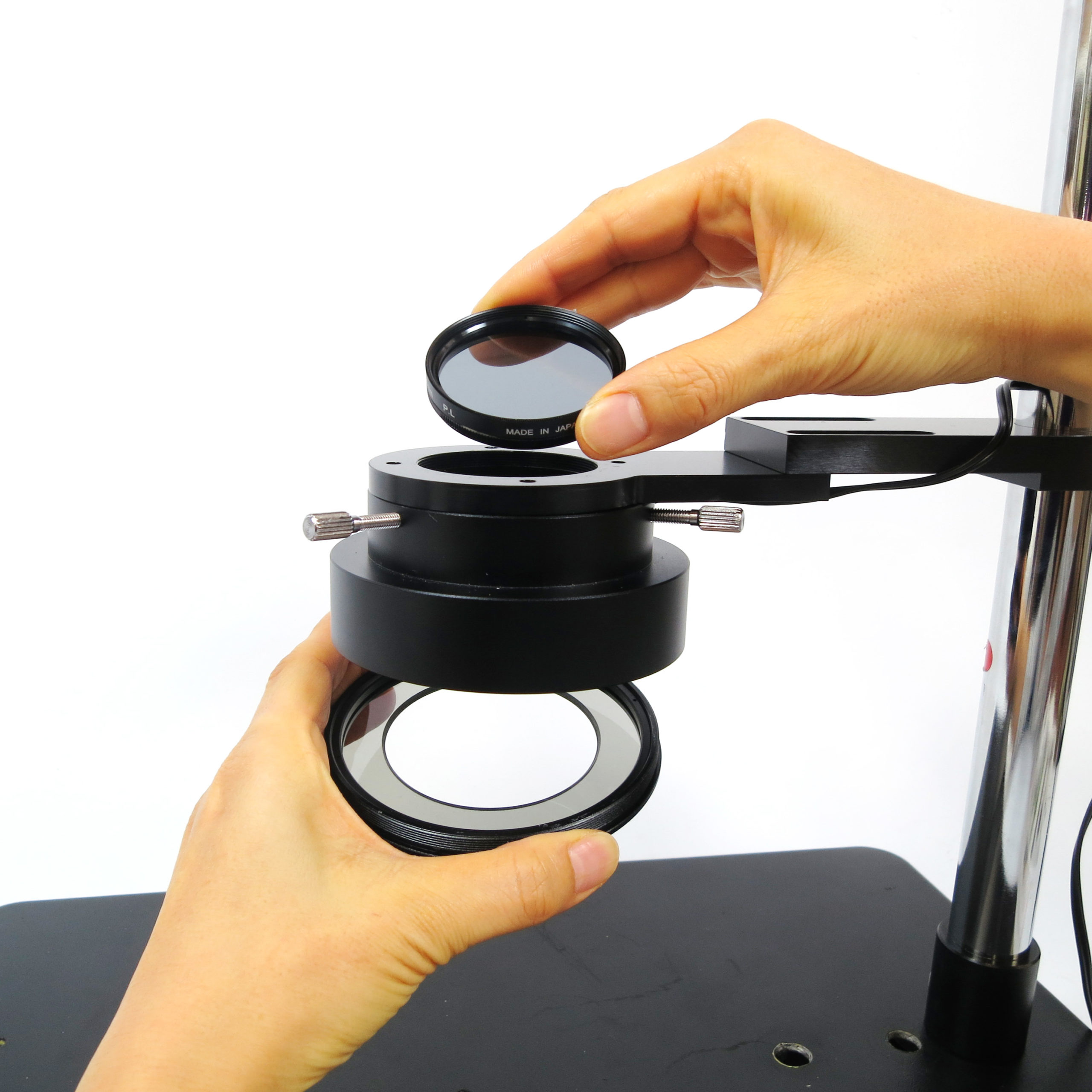
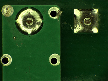
■ Polarizing filters on both the ring light and lens illumination |
|
| Microscope halation removal set GR-HL
By attaching polarizing filters to both the incident light side and the light-emitting side, halation can be significantly reduced. |
 |
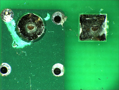
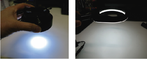
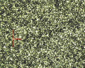
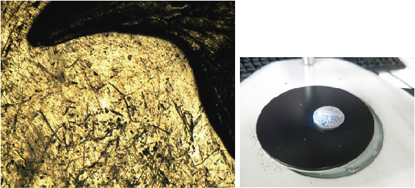
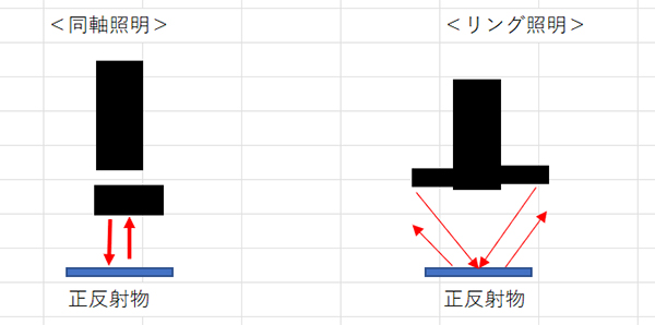
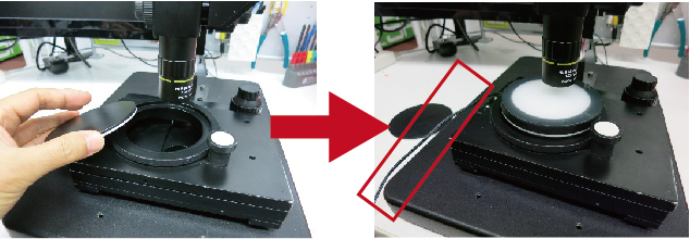
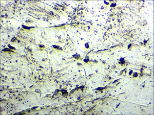
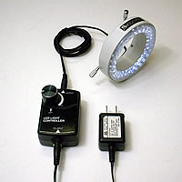
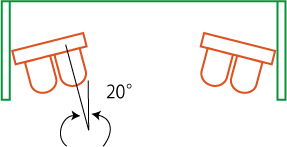
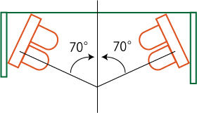
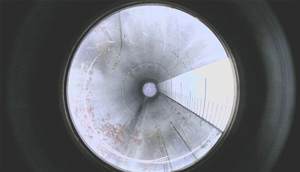
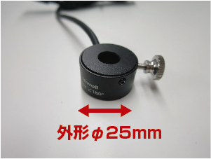
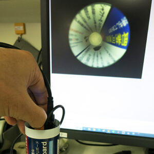
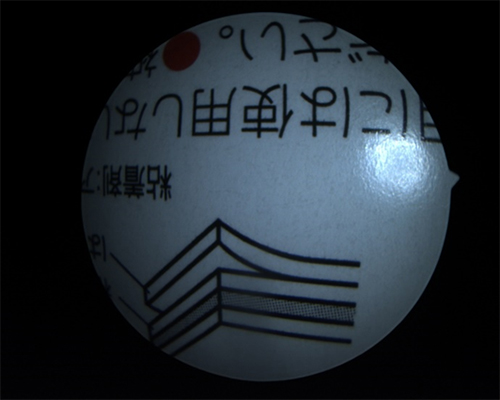
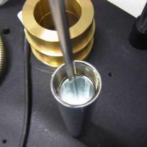
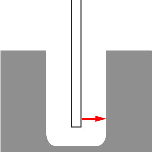
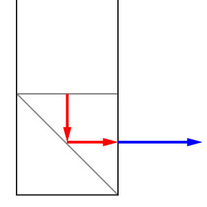
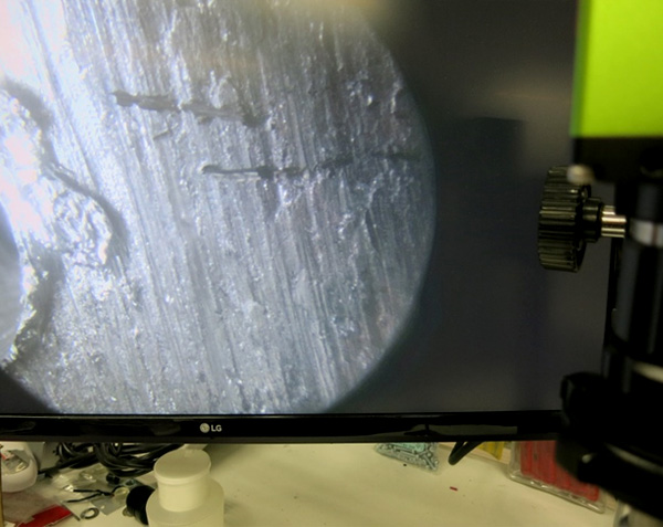
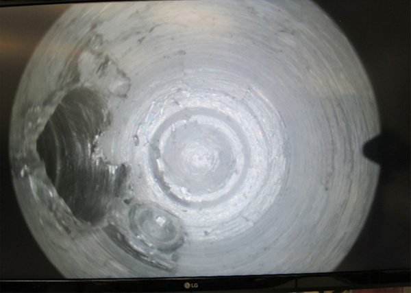
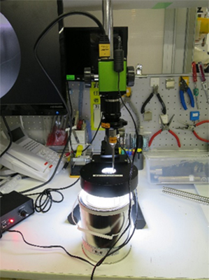
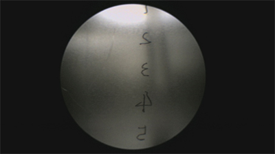
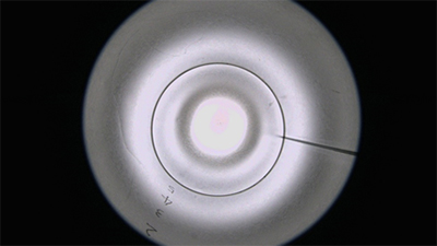
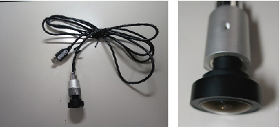
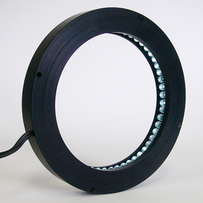
■ Low-angle LED light |
|
| Low-angle LED ring light GR56-N
|
|
|
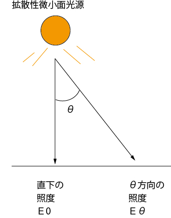
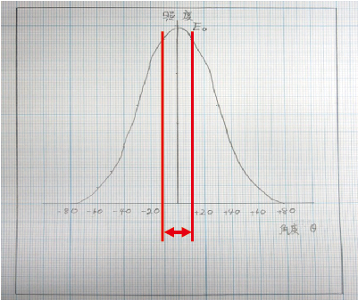
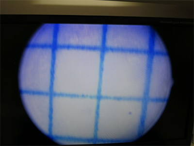
(※) By using a low-angle ring light and adjusting the setup so that the light does not directly hit the object (illuminating the substrate with diffuse light only), observation is carried out with diffuse light. However, due to the use of only diffuse light, the illuminance cannot be increased significantly, and the magnification cannot be set very high.
|
 |
 |
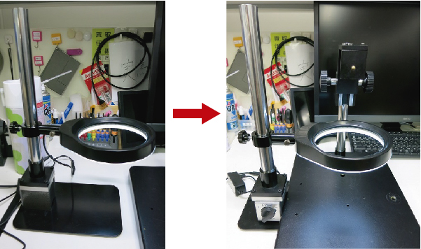
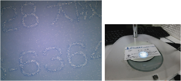
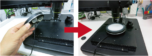
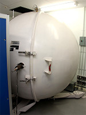
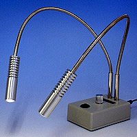
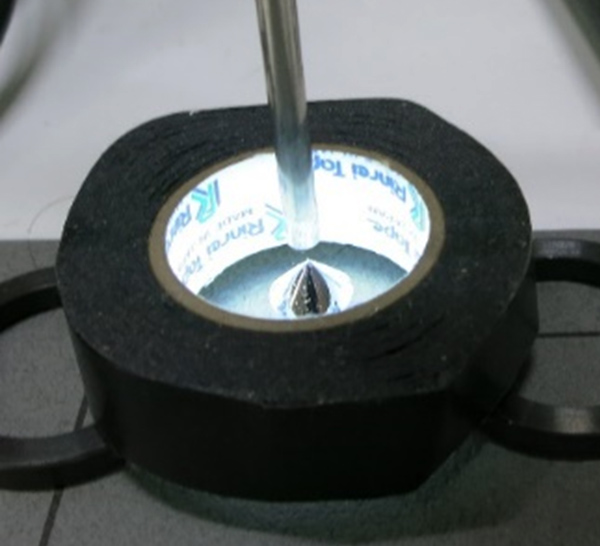
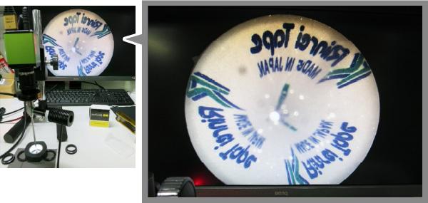
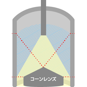
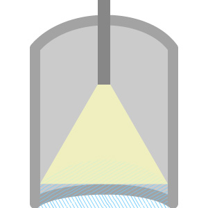
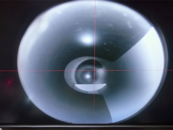
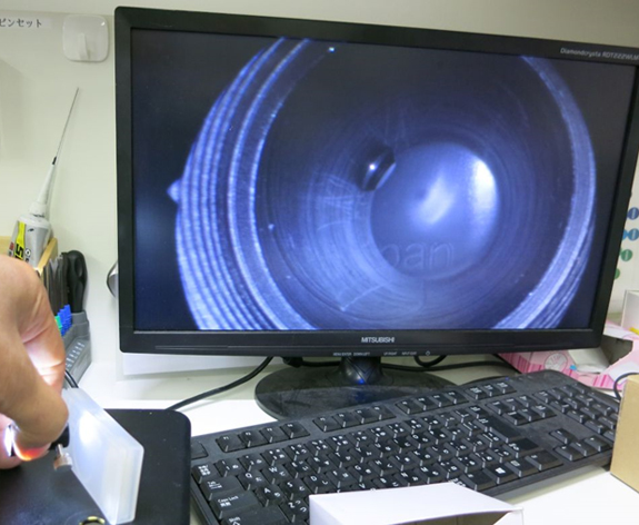
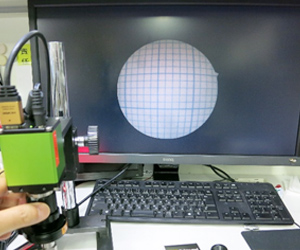
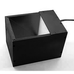
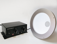
■ Dome-type light |
|
|
Dome-type light DC-170W
|
|
 |
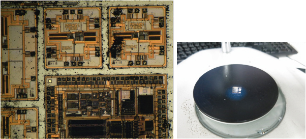
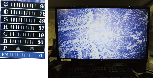
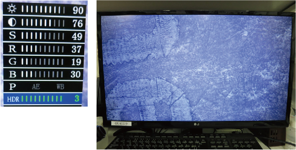
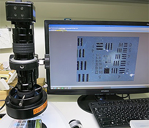
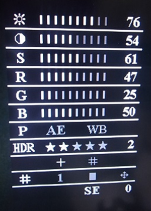
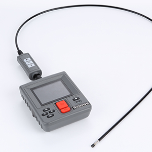
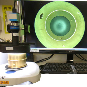
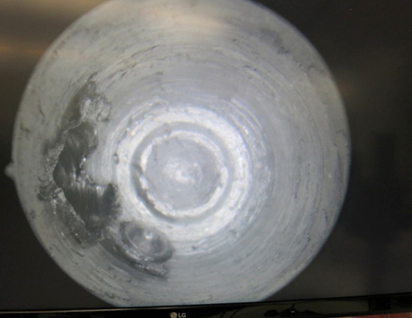
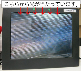
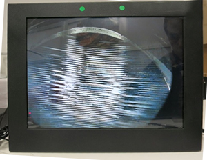
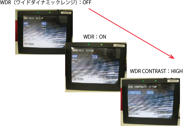
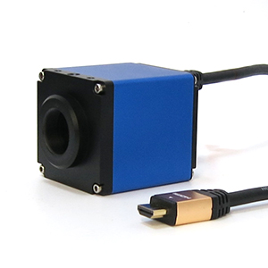
■ HDR (High Dynamic Range) function of a high-definition camera |
|
|
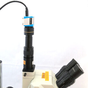
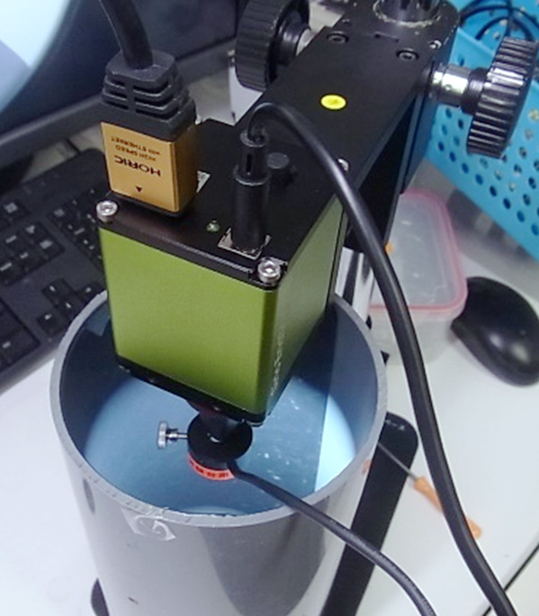
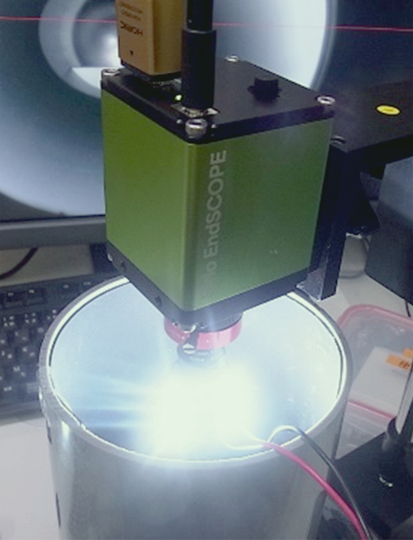
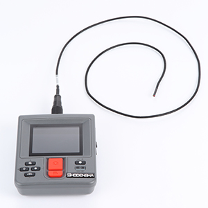
High-definition camera GR200HD2
|
 |
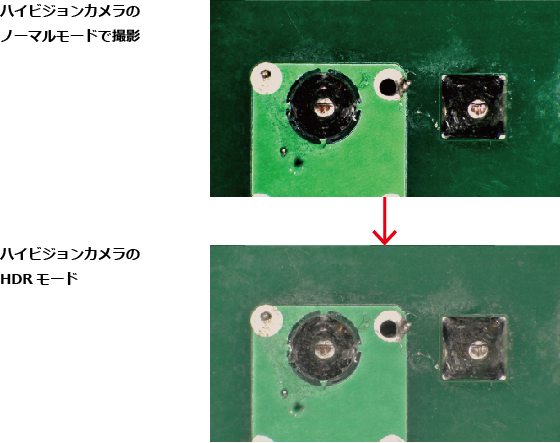
The brightness is averaged, sacrificing contrast, in order to expand the dynamic range.