・What is welding?
Welding is “joining two metal base materials together using heat or pressure.”
Or “joining by adding filler metal and using heat or pressure.”

The main methods used are heating with electricity, arc discharge, gas, plasma, laser, etc.
The length of the weld leg (bead) formed at the weld (weld overlay) at this time has a large effect on the strength of the weld joint.
Evaluation of welding
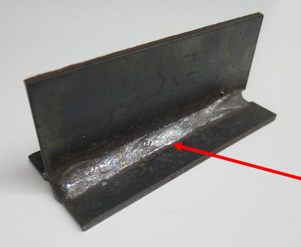
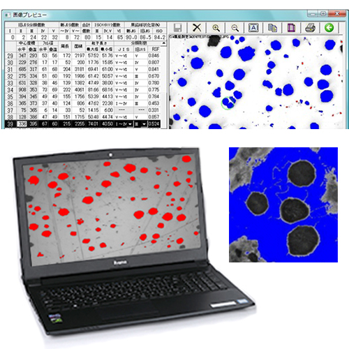
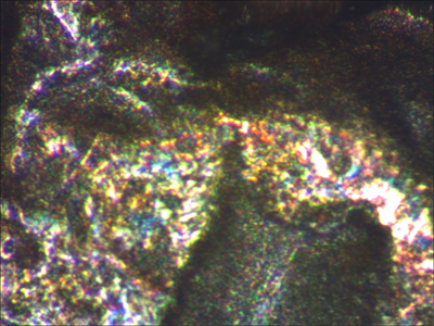
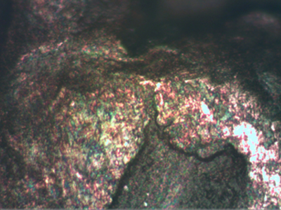
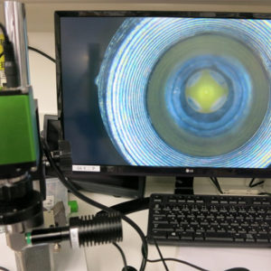
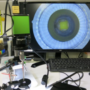
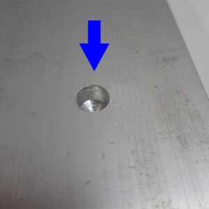
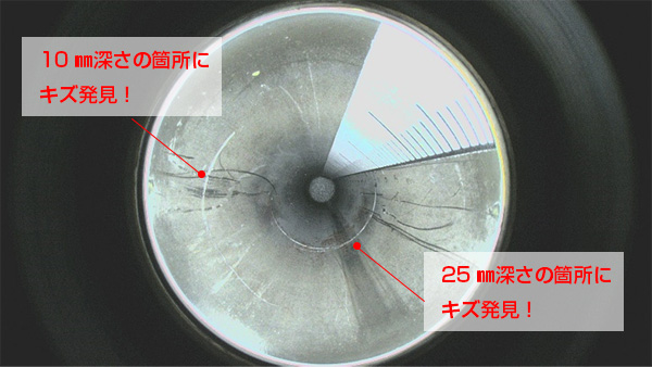
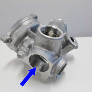
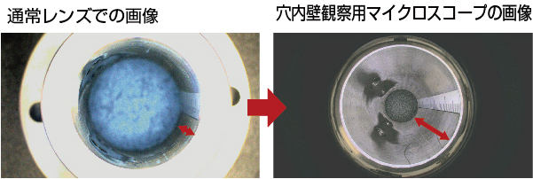
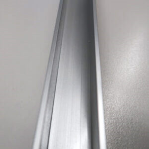
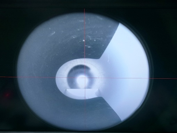
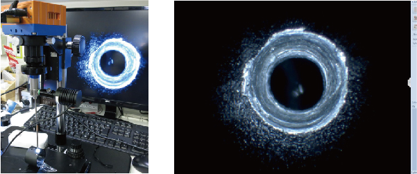
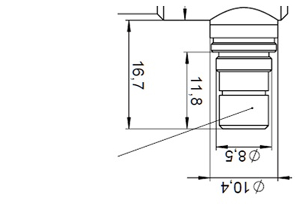
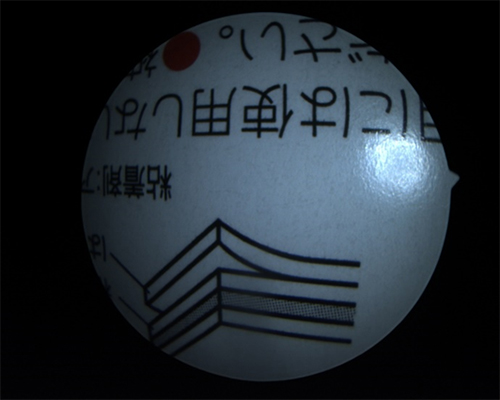
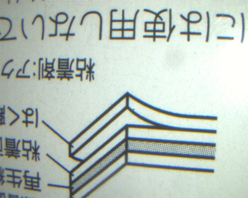
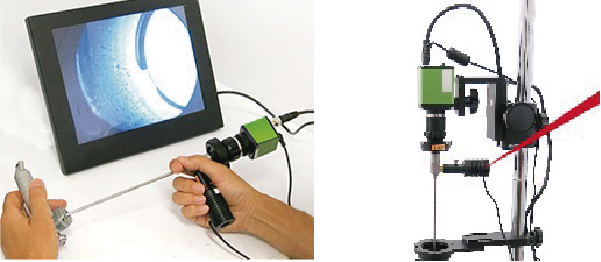
The part with the red arrow in the image is the weld bead.
The external shape and dimensions (width, length, height) of this weld bead vary depending on the welding conditions.
Depending on the shape of the weld bead, it is possible to evaluate whether proper welding was achieved and whether there are any welding defects.
There are following types of welding defects:
・Insufficient surplus
· Overlap
· undercut
· pit
・Crack etc.
To evaluate this weld bead, it is necessary to measure its three-dimensional shape.
・What is inspection in welding?
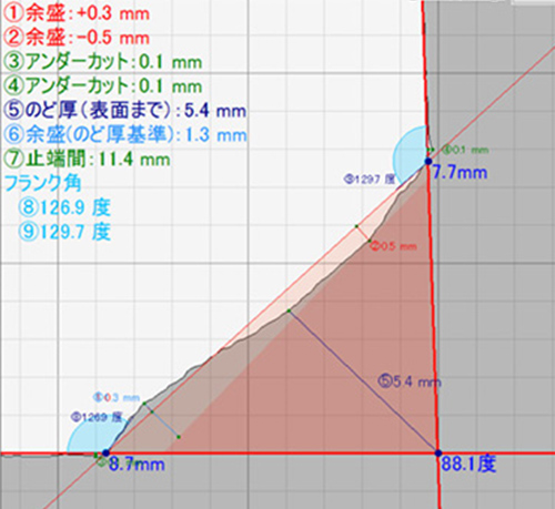
The dimensions specified in the cross section of the weld are the “throat thickness,” which is the minimum thickness of the weld bead, and the “penetration amount” and “penetration depth,” which are the length from the molten peak of the metal base metal to the metal base metal surface. etc. are stipulated.
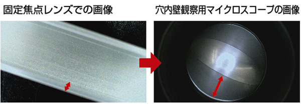
⇒Click here for information on welding penetration measurement
Dimension regulations include the minimum length from the weld root, which is the base of the joint, to the toe of the weld bead, “leg length.”
This leg length is one of the criteria for determining the optimal bead width
.
・Improved efficiency in measuring the shape and length of weld leg length (bead)
Bead inspection is required to ensure welding quality.
The common testing methods are:
・Visual comparison with good sample
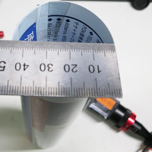
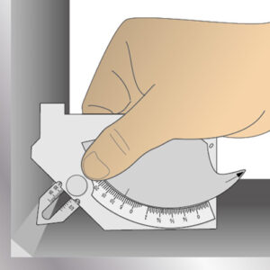
・Method of visually comparing with welding gauge
However, these require a high level of skill and time from the person in charge of the inspection, and judgments vary depending on the person.
Additionally, the welding-specific gauge measurement method requires measurements at multiple locations, which is inefficient.
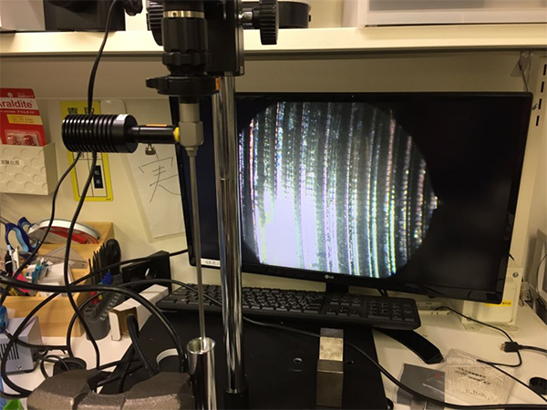
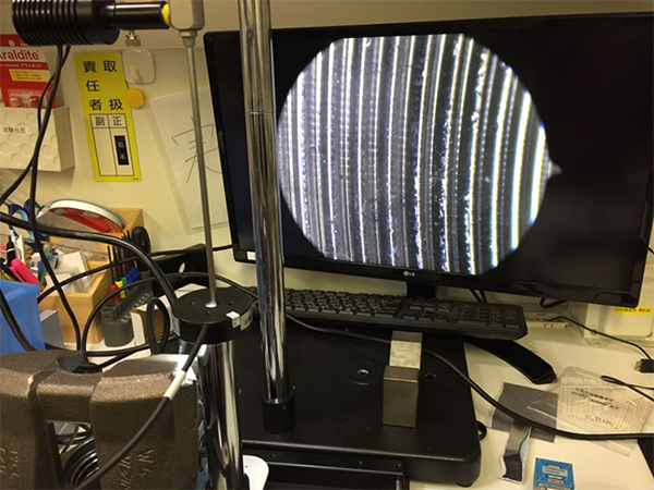
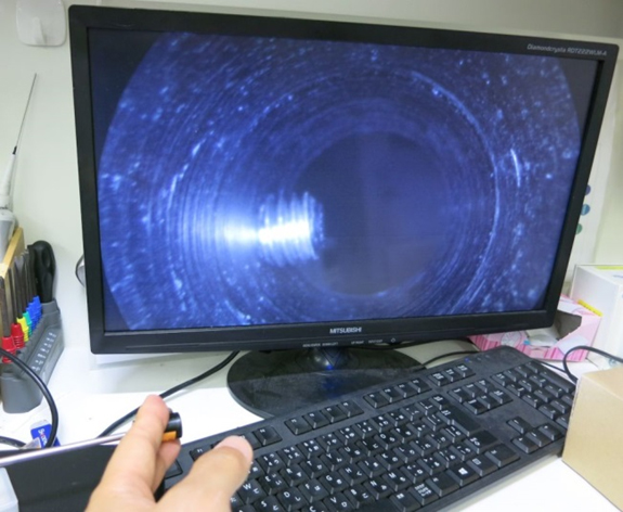
<Image of welding gauge measurement>
By using the products below, you can solve these weld bead measurement problems.
・Recommended products for measuring weld leg length (beat)
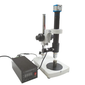
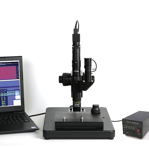
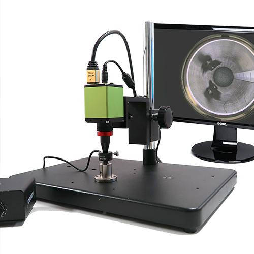
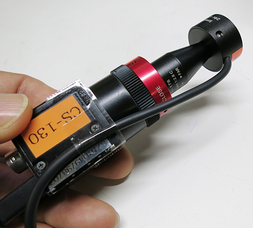
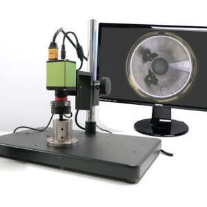
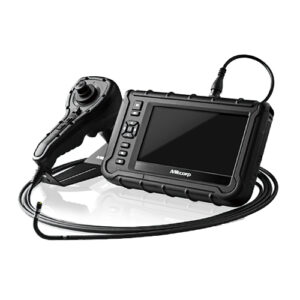
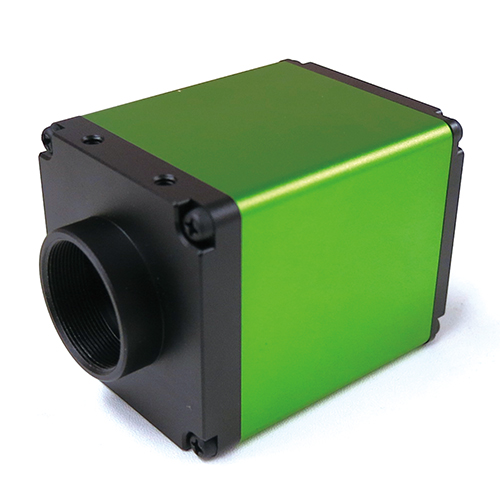
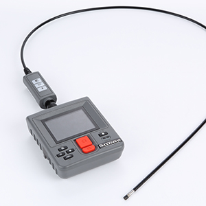
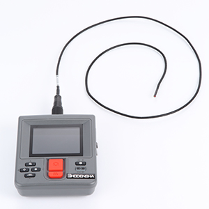
[Welding leg length handy 3D scanner CSM-HS10WL]
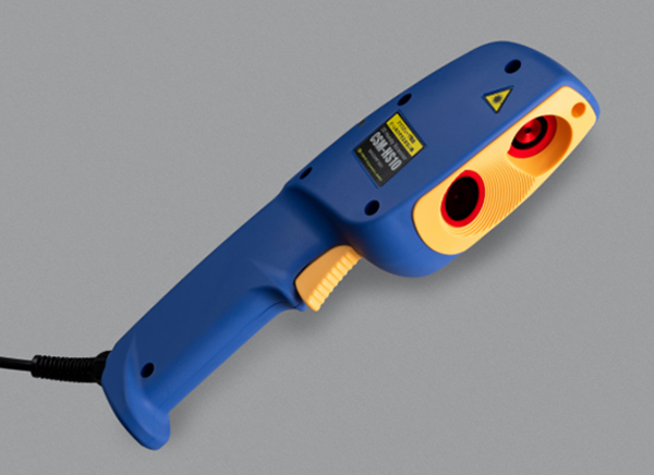
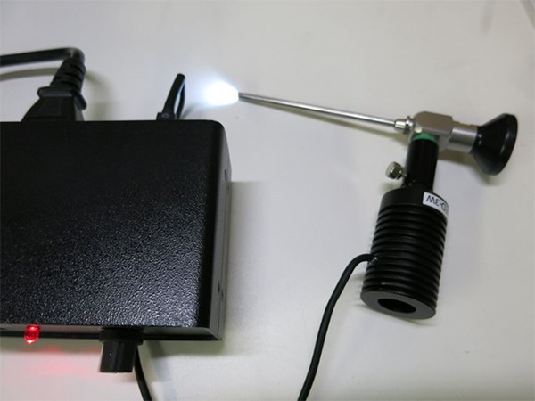
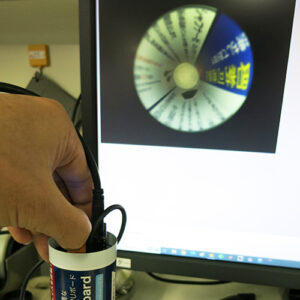
This product is a 3D handy scanner that can instantly measure the cross section of a weld bead in a non-contact, non-destructive manner by simply shining a laser on the weld area you want to measure.
* Penetration inside the weld and blowhole inside the weld cannot be measured.
Non-contact optical cutting method that operates a trigger switch eliminates the need for measuring with a straight scale or welding gauge.
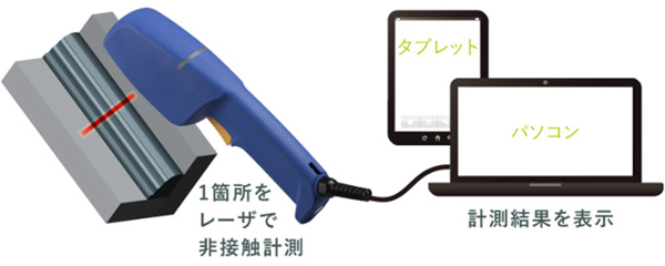
You can 3D scan the area where the laser is irradiated onto the welded part, allowing for high-precision measurement of its three-dimensional shape and displaying cross-sectional views. This method enables instant, non-destructive measurement of weld bead (bead length) without human error or variation.
~Features of this equipment~
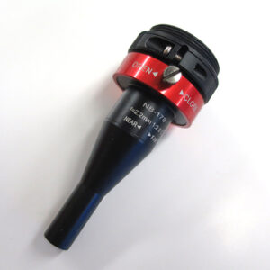
Feature 1: User-friendly handheld 3D scanner
– Easy to handle as a handheld device, the 3D handheld scanner
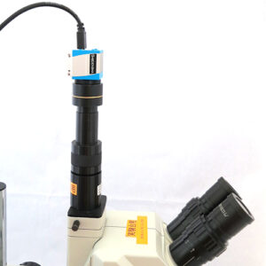
– Simply connect to a PC or tablet via USB. Once the welding measurement software installed inside the unit is installed on your computer, it can be operated immediately.
– Easy to handle as a handheld device, it can measure even large or heavy objects and fit into narrow spaces, making it suitable for previously difficult-to-measure targets
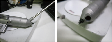
Feature 2: Simply aim and pull the trigger at the desired measurement position to initiate measurement.
- – When measuring weld beads, traditional methods require the use of calipers or specialized welding gauges, but with this equipment, pinpoint measurements are possible with a single laser shot.
– Simply aim at the weld bead (raised area of the weld mark) and trigger the switch to measure.
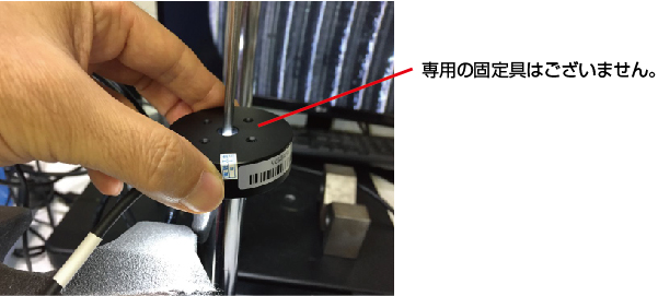
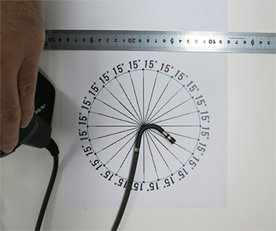
– Includes a detachable guide rod for convenient adjustment of distance and angle during measurement.
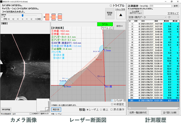
– Using optical sectioning, you can easily perform 3D measurements of 12 points on the weld bead, including “leg length,” “undercut,” “joint angle,” and “excess weld metal.”
- Feature 3: Instant display and saving of leg length measurement results on the PC screen
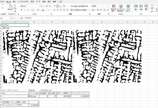
- – Measurement results can be saved as files and utilized in Excel®.
– Numerical values are displayed simultaneously during measurement, allowing for accurate and error-free records.
– Eliminates the need for error-prone handwritten records and enhances tamper-proofing.
– Ensures traceability of measurements.
~Even more convenient features~
Function 1: Equipped with a measurement mode convenient for welding bead (leg length) inspection as standard.
・Measurement of fillet welds

Measurement of corner radius
Measurement of butt welding
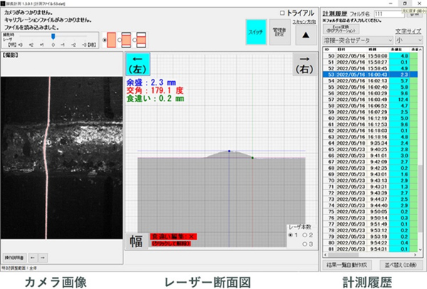
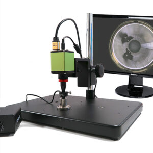
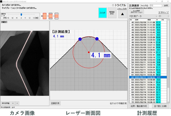
Feature 2: Display of camera images, laser cross-sectional views, and measurement results on a single screen
-
– Camera Image:
Display of the captured video from the camera.– Laser Cross-sectional View:
Clear display of measurement results with numerical values and cross-sectional diagrams.– Measurement History:
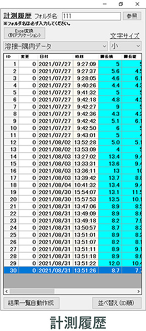
Display of numerical results from measurements.
Function 3: Measurement history can be output in EXCEL®
Feature 3: Measurement history can be exported to Excel®.
Feature 4: QR code scanning
By scanning QR codes or barcodes, you can easily link them with measurement items and manage measurement results through QR codes. Additionally, combining QR codes with cloud services enables visualization and digital transformation (DX) of welding operations.
・Summary
If you want to significantly improve and streamline the challenging task of accurately measuring weld bead shapes,
the **Weld Leg Length Handy 3D Scanner CSM-HS10WL** is extremely convenient.
– Eliminates variability in measurements by humans, enabling quantitative measurements.
– Capable of reading QR codes and linking with product data.
– Non-contact measurement for precise 3D shape measurement of objects.
– Visualizes anomalies in weld beads using color mapping.