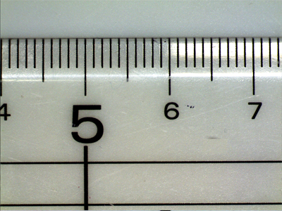
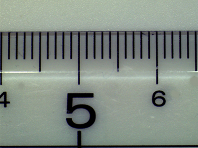
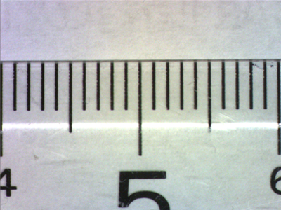
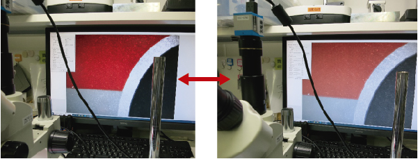
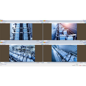
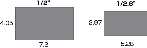
When using a lens with the same magnification, the smaller the number of inches in the image size, the larger the magnification and the narrower the field of view.
Take a look at the pictures below.
The lens, monitor, and focal length are taken under the same conditions.
1/2 inch camera
1/2.5 inch camera
1/3 inch camera
You can see that the 1/3 inch camera has a narrower field of view than the 1/2 inch camera.
Also, when selecting a lens, it is necessary to check the compatible image sensor size of the camera.
Please note that if you select a lens that is smaller than the camera’s compatible image sensor size, a phenomenon called vignetting may occur.
You can see black areas (vignetting) in the four corners of the screen.
We can also help you with the selection of lenses and cameras. For more information, please contact Technical Support.
The IMX183 has a pixel size of 2.4×2.4 μm and is a rolling shutter sensor.
The pixel size is as small as 2.4 μm and the sensor size is 1 inch. SONY’s unique back-illuminated technology achieves excellent image quality with high sensitivity, making it ideal for building optical systems.
SONY CMOS Sensor IMX183 specifications
Number of pixels: 20 million pixels (resolution 5472×3648)
Pixel size: 2.4μm×2.4μm
Sensor Size: 1 inch
Shutter method: Rolling shutter
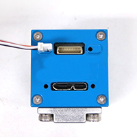
USB3 Vision Camera (USB3.0, 20 million pixels, color) CS2000-C
USB3 Vision Camera (USB3.0, 20 million pixels, monochrome) CS2000-B
1-inch GigE camera (20 million pixels, color) EG2000-C
1-inch GigE camera (20 million pixels, monochrome) EG2000-B
The IMX226 has a pixel size of 1.85×1.85 μm and uses a rolling shutter method.
SONY’s Pregius series is characterized by high sensitivity and low noise performance. The sensor is 1/1.7″ in size and is available with standard and affordable 2/3″ C-mount lenses.
SONY CMOS sensor IMX226 specifications
Number of pixels: 12 million pixels (resolution 4000×3036)
Pixel size: 1.85μm×1.85μm
Sensor size: 1/1.7 inch
Shutter method: Rolling shutter
USB3 Vision Camera (USB3.0, 12 million pixels, color) CS1200-C
USB3 Vision Camera (USB3.0, 12 million pixels, monochrome) CS1200-B
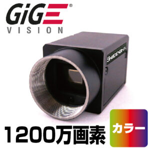
GigE camera (12 million pixels, color) EG1200-C
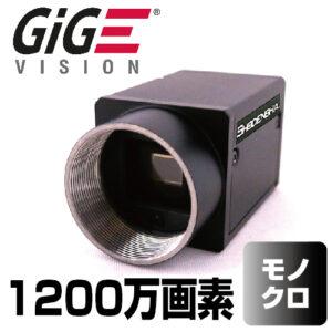
GigE camera (12 million pixels, monochrome) EG1200-B
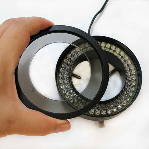
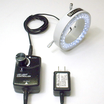
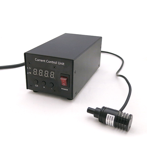
●Inner diameter φ70mm, tip inner diameter φ60mm, outer diameter φ96mm ●Includes replaceable polarizing filter and diffuser ●Dimmable with control box ●Can be attached to microscopes, microscopes, etc.
The IMX178 is a rolling shutter sensor with a pixel size of 2.4×2.4 μm.
SONY’s Starvis series supports high sensitivity even in low-light environments by increasing the gain. The sensor has a resolution of 6 million pixels, a size of 1/1.8 inch, and a wide dynamic range, making it suitable for a variety of applications.
SONY CMOS sensor IMX178 specifications
Number of pixels: 6 million pixels (resolution 3072 x 2048)
The IMX264 has a pixel size of 3.45×3.45 μm and the sensor uses a global shutter method. The Pregius series manufactured by SONY is characterized by high sensitivity and low noise performance. This sensor is 2/3 inch in size, has a wide dynamic range, and has a resolution of 5 million pixels, making it suitable for a variety of applications.
SONY CMOS sensor IMX264 specifications
Number of pixels: 5 million pixels (resolution: 2448 x 2048)
Pixel size: 3.45×3.45µm
Sensor size: 2/3 inch
Shutter method: Global shutter
GigE camera (Sony 5 million pixels, color) EG501-C
GigE camera (Sony 5 million pixels, monochrome) EG500-B
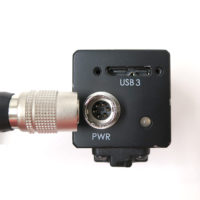
■ What are the external trigger terminals for industrial cameras?
Many industrial cameras have external trigger terminals.
USB Camera DN Series
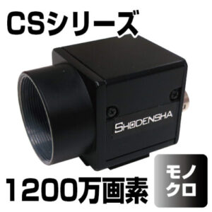
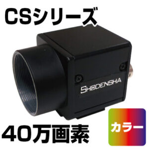
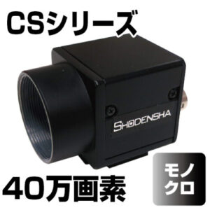
USB Camera CS Series
This trigger pin is used to control the timing of still image shooting and video recording with a sensor or PLC (programmable logic controller).
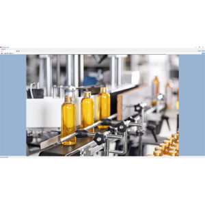
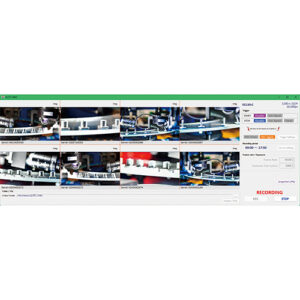
Watch the video brief image below.
System Example Video
Of course, even if you don’t use an external trigger, you can use the included application software to save still images and record videos.
However, in actual production lines, it is common to shoot and record at the timing of the object to be photographed, and there are many situations where an external trigger terminal of an industrial camera is required.
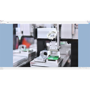
Watch the video brief image below.
■ How to use the external trigger terminal?
When using external trigger terminals, there are various ways to use them depending on the customer’s production line.
In addition to simply saving still images and recording videos, it can be used for a variety of purposes, such as recording videos before and after a problem occurs, or shooting and recording with multiple cameras.
Therefore, when using an external trigger pin, it is basically assumed that the customer will program it himself.
Industrial cameras usually come with an SDK (Software Development Kit) for development, which is used to create programs.
■ Still image storage with external trigger
I mentioned that “basically create a program”, but if it is a simple function, application software can be used.
By using it, you can build a system without any knowledge of programming.
Among them, we will explain the most basic “saving still images with an external trigger”.
Even with the simple function of “saving one still image when an external trigger signal is input”, there are two main methods.
And the time display between the trigger and the next trigger is different.
(1) A still image taken with the latest trigger is displayed between the trigger and the next trigger.
・Saved images can be reliably checked in real time.
Even lines with movement can be visually checked using still images.
・When shooting with multiple cameras at the same time, it is possible to shoot perfectly in sync.
We offer the following software:
Trigger Shooting Software
Hi TriggerF Light
High-performance trigger shooting software
Hi TriggerF Pro
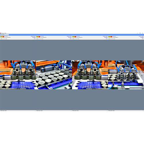
(2) A method is adopted in which live video is displayed between the trigger and the next trigger.
・Since the live image is always displayed, it is possible to monitor the status of lines other than the object.
・When shooting with multiple cameras at the same time, multiple frames may be out of alignment.
We offer the following software:
Four-screen display shooting software
Hi TriggerQ
■ Video recording with external triggers
In the case of video recording, there are the following two types.
(1) Use the start trigger and stop trigger as triggers
(2) Use only the start trigger as a trigger
In the case of (1), only a simple recording function is provided.
In the case of (2), various functions are available.
In addition to simply recording the specified time by timer control from the trigger, you can also record before and after the trigger (operation like a drive recorder). It is useful for event analysis when a problem occurs.
We offer video recording software that allows you to use both Start/Stop triggers, timers, etc.
Long-Duration Recording Software
Hi TriggerRec
Software to record video before and after the trigger
Facility monitoring drive recorder
Hi TriggerWatcher
■ Software Development
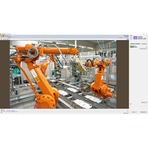
Robots, conveyors, drones, AI-based automated inspections, etc., can be linked to external triggers to become independent automated equipment for the first time.
At Shodensha, we help with system development and software development using cameras.
Differences between C-mount industrial cameras and webcams
Industrial cameras are used for visual inspection and observation.
This section introduces the differences between C-mount industrial cameras (FA cameras) and web cameras.
Any of the following problems are bound to occur in human visual inspections and counts.
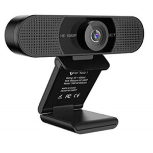
Webcam Features
When people hear the word “USB camera,” they tend to think of a web camera.
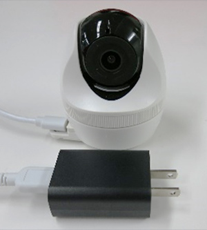
They are sold on the Internet and at mass retailers, and simply by connecting to a PC, an image is projected.
They are sold at very reasonable prices and are easy to obtain.
Areas where webcams are used
However, webcams are rarely employed in industrial or industrial settings.
The most likely reason is that the lens is not interchangeable.
A web camera basically has a built-in lens.
The camera and lens are included in a single case.
The price is very reasonable, including the lens, but the disadvantage is that the lens is not interchangeable.
Just as cameras have pixel counts, lenses also have corresponding pixel counts.
Recently, cameras with high pixel counts are relatively inexpensive, but lenses are not.
Even if a web camera claims to have 5 megapixels, the lens probably has less than 1 megapixel.
Therefore, the image is not clear and blurred despite the high pixel count.
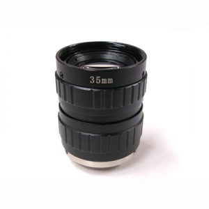
Basically, industrial cameras are divided into a camera body and a lens.
What is a useful industrial camera…
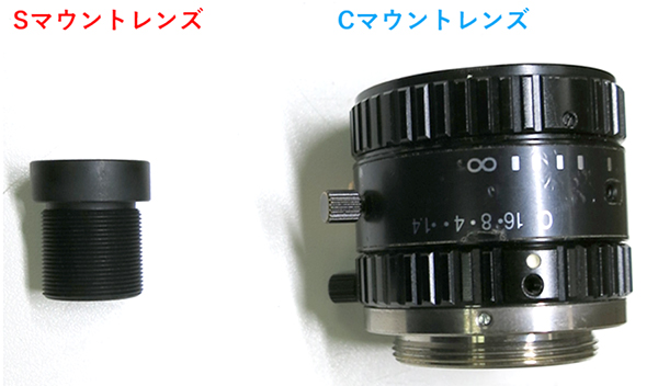
There are several standards for industrial cameras called C-mount, CS-mount, and S-mount.
Lenses that fit these mounts are separately prepared and mounted.
The ability to select lenses allows for a wide variety of options, such as the area to be projected and the distance the camera needs to be away from the object.
In addition, the number of pixels of the lens can be selected to match the number of pixels of the camera, resulting in a clearer image.
How to choose an industrial camera
Industrial cameras:
1.USB camera
2.GigE camera
3.UVC camera
4.HDTV
5.High-speed camera
There are various types, such as the following, to choose from depending on the application.
Industrial cameras are chosen in industrial and industrial settings because they offer a very high degree of freedom in terms of the images that are projected.
There are various types of industrial cameras such as USB cameras, GigE cameras, and Hi-Vision cameras.
In this issue, we will introduce the advantages and disadvantages of each connection method.
■USB camera
It can be connected to a PC via a USB port and used for a variety of applications.
It is the most standard industrial camera used in a variety of situations.
<Merits>
High versatility and easy connection.
Low cost.
Many applications (software) for USB cameras are available, so you can choose the application according to what you want.
High frame rate is possible by selecting USB3.0 type.
Wide lineup of cameras with different pixel counts.
<Demerits>
Short for cable.
Depends on PC specs.
■GigE Camera
The camera is connected to a PC using a LAN port, making it similar to a USB camera.
The use of a LAN cable ensures stable communication and long-distance connection.
<Merits>
Long cable lengths, 100 m for LAN, and even longer distances with optical fiber.
Communication is stable and noise-resistant.
Operable at a frame rate equivalent to USB 3.0.
<Demerits>
Need to provide a POE interface for connection.
Few applications are as versatile as USB cameras.
■HDMI Camera
It can easily project images without the use of a PC.
It is specialized for monitoring and has excellent color reproduction of video images.
<Merits>
Directly connected to the monitor for easy use.
Some types of cameras are loaded with memory and come with a measurement function, allowing measurement without a PC.
High color reproducibility and frame rate make them ideal for monitoring such as inspections.
Some models have high camera sensitivity, so they can be combined with borescopes.
<Demerits>
If you want to add functions later, you need to buy new hardware.
External equipment may be required to save still images.
The pixel size of this IMX265 is 3.45 x 3.45μm, and it is a global shutter type sensor.
Sony’s Pregius series is known for its high sensitivity and low noise.
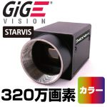
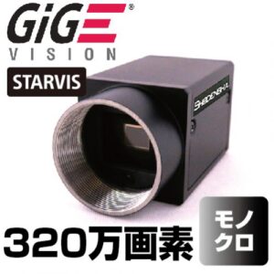
The resolution is 3.2 million pixels and the sensor size is 1/1.8 inch, so there are many lens options. It can be said that this model has a good balance between image quality and frame rate (speed).
SONY CMOS sensor IMX265 specifications
Number of pixels: 3.2 million pixels (resolution: 2048 x 1536)
Pixel size: 3.45×3.45µm
Sensor size: 1/1.8 inch
Shutter method: Global shutter method
GigE camera (Sony 3.2 million pixels, color) EG320-C
GigE camera (Sony 3.2 million pixels, monochrome) EG320-B
The pixel size of this IMX287 is 6.9 x 6.9μm, and it is a global shutter type sensor.
SONY’s Pregius series is known as a high-speed sensor. If you are using the CCD sensor ICX618, as a transition to a CMOS sensor, this IMX287 has a similar pixel size and resolution, minimizing changes to peripherals such as lenses.
Furthermore, despite the low price, the sensor performance has been significantly improved.
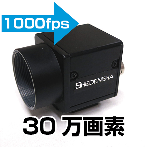
SONY CMOS sensor IMX287 specifications
Number of pixels: 400,000 pixels (resolution 720 x 540)
Pixel size: 6.9×6.9μm
Sensor size: 1/2.9 inch
Shutter method: Global shutter method
USB3 Vision camera (USB3.0, 400,000 pixels, color) CS41-C
USB3 Vision camera (USB3.0, 400,000 pixels, monochrome) CS41-B
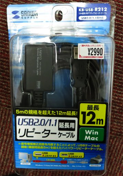
The USB2.0 standard usually recommends a length of up to 5m.
However, in reality, cables that exceed this length are sold by major manufacturers. (Generally speaking, it is said that there is no significant effect on communication speed up to about 10m).
In addition to simple extension cables, USB cables with repeater functionality are also available. These are also commonly referred to as active cables.
Multiple companies sell these products, but the product in the photo is Sanwa Supply Co., Ltd.’s KB-USB-R212 [12m extension USB active repeater cable].
According to USB cable standards, the maximum connection distance between devices is usually 5 meters. However, by using this “USB cable with repeater function”, you can connect devices with a cable longer than 5m. The product in the photo can be extended up to 12m using this cable.
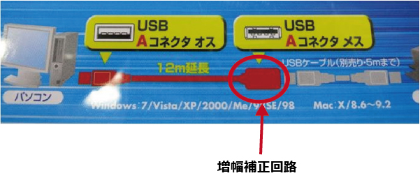
This cable has a built-in signal amplification correction circuit. This circuit compensates for signal attenuation and allows cable extension. This cable can be extended over 12m. In that case, wire as shown below.
I tried connecting a 12m USB cable with repeater function (product in the photo) and the cable (1.8m) that came with the camera to our USB camera, and it worked without any problems. However, the instruction manual for the USB cable with repeater function (product in the photo) states, “To ensure stable operation and recognition, we recommend that the connected USB device be a self-powered device.” there was.
Of course, there are also active cables that use USB power (bus power). It is convenient and does not require a power supply, but if your PC’s power supply is weak, stability may be a problem.
Extending the USB cable will cause a voltage drop, so we recommend that you always check the operation when using devices that are powered by a PC (including our USB cameras).
If you want to use multiple cameras, you need a high-performance PC. (The use of laptops is not guaranteed.) In general, as the resolution and number of cameras increase, so do the required specifications of the PC. The following are recommended specs, but this is a guide.
・CPU: 12th generation or later Intel Core i7 (12th generation or later Intel Core i9 is recommended for 4 or more cameras)
・RAM: 16 GB or more
If you’re recording for a long time, add the above specs to a GPU like the RTX 3070.
If you have more than 4 cameras, we recommend adding a USB board or a LAN board for GigE cameras to account for bandwidth limitations. To add a board, the required PCIe slot must be free.
Also, the amount of storage space you need depends on your camera’s resolution, fps, and recording time. The following is an estimate of the storage time that can be stored on each camera when using 1TB of storage.
1TB SSD
400,000 pixels 30fps
Compression
160h
Non – compression
6h45min
1.3 million pixels 30fps
Compression
48h
Non – compression
2h
5 million pixels 30fps
Compression
11h
Non – compression
28min
※If there are 2 cameras, the time will be 1/2, and if there are 4 cameras, the time will be 1/4. When performing compressed recording, it may be possible to secure sufficient writing speed with an HDD depending on the number of cameras and fps.
When recording with multiple cameras at the same time, there may be a deviation of several frames between cameras due to factors such as camera clock and component deviations, aging, and the ambient temperature at which they are used.
Due to the complex interplay of these factors, it is difficult to give a specific amount of deviation, but as a general guideline, if you record for more than 8 hours, there may be a deviation of about 1 to 2 seconds.
Synchronous recording is a method that completely eliminates the above deviations and makes recordings without deviations. Synchronous recording uses not only a camera, but also a synchronous signal generator.
Multiple cameras are fed into the signal from the synchronous signal generator at exactly the same time, and only the frame at the time when the signal is entered is recorded, resulting in perfectly synchronized recording and not being affected by the camera clock or environment.
Multi-unit video recording software
Evidence: Rec4 / Rec8
Software that allows “multiple cameras” to record “simultaneously” is ideal for creating evidence and evidence of problems that arise in the field.
Fully synchronized recording set for USB/GigE cameras with multiple units (long-term recording software)
HiTriggerSyncRec2
Software that enables “fully simultaneous and synchronous recording” with “multiple cameras” is also available.
USB/GigE Camera Fully Simultaneous and Synchronized Facility Monitoring Drive Recorder
HiTriggerSyncWatcher2
Software that enables “fully simultaneous and synchronous recording” with “multiple cameras” is also available.
Due to space constraints, it may be necessary to configure the camera and lens in a compact manner.
In such cases, compactness can be achieved by choosing an S-mount lens that is smaller than a C-mount or CS-mount lens.
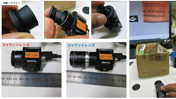
In order to use S-mount lenses, you need to attach a conversion adapter to the camera.
However, there is a caveat.
With S-mount lenses, the focus is adjusted depending on how well it is inserted into the camera.
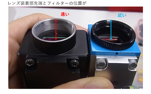
Cameras usually have an infrared cut filter or a protective filter in front of the sensor.
In some cameras, the distance between the filter and the lens mount is close, and the lens may interfere with the filter when focusing, resulting in a lack of focus.
It is necessary to actually try and check whether the S-mount lens can be attached and used with the camera.
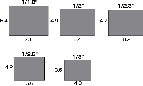
When using the same lens, the smaller the size of the image sensor, the narrower the field of view. In addition, the size of the image sensor is a necessary factor in the calculation of the field of view and the selection of the lens. (More on this later.)
The size of a single pixel can also be calculated from the size of the image sensor
For example, if the image sensor size of 1.3 million pixels (1280 dots × 1024 dots) is 1/2.5 inch, the horizontal orientation is 5.6 mm and the vertical direction is 4.2 mm.
In this case
Horizontal 5.6mm/1280dot=0.0044mm/dot
Vertical direction is 4.2 mm/1024 dot = 0.0041 mm/dot.
Meaning of image sensor size
Usually, when we say size on a monitor, we are referring to the length of the diagonal.
However, the size of the image sensor is not the length of the diagonal.
For example, in the 1/2.5-inch image sensor with 1.3 million pixels mentioned earlier, the horizontal direction is fixed at 5.6 mm and the vertical direction is fixed at 4.2 mm.
If we calculate from this figure, then the diagonal length will be 7 mm. But the actual diagonal length of 1/2.5 inch is 10.16mm.
This is due to the influence of the size notation of the diameter of the imaging tube in the era when vacuum tubes were used in the past, and the image sensor is also matched to the size of the imaging tube, and that notation remains as it is.
Actual image sensor size
4:3 horizontal and vertical image sensor
19:6 horizontal and vertical image sensor
Actual use of image sensor size
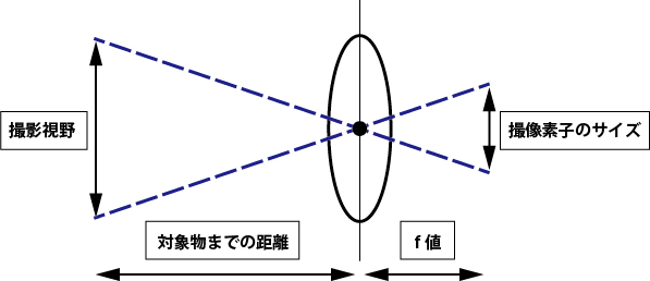
When choosing a lens or calculating the distance to an object, the size of the image sensor is required.
(1) In the case of a CCTV lens (fixed focal length lens)
The following factors are required to calculate the required lens based on the size of the object: the size of the camera’s image sensor and the distance to the object (W.D.).
For example, if the distance to the object is 1 meter and the vertical field of view is 300 mm, what focal length lens should you choose? (Let’s assume we use a 1/2 inch camera).
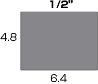
The image sensor size of a 1/2 inch camera is as follows.
Focal length (f) = (distance to object (mm) x vertical size of image sensor (mm)) / vertical field of view = (1000mm x 4.8mm) / 300mm = 16mm
Therefore, choosing a lens with a focal length of 16mm will ensure the desired vertical field of view. Horizontal field of view can be calculated similarly.
Note that once you know the vertical or horizontal field of view, you can easily calculate the other field of view. A square image sensor has an aspect ratio of 4:3, so in the above case, the horizontal field of view is 300mm x 4/3 = 400mm.
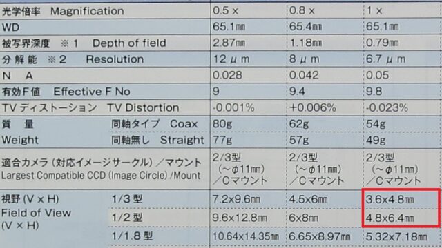
(2)For macro lenses
Lenses that magnify objects often have a fixed focal length.
In this case, the characteristics of the lens cannot be expressed by the focal length (f value).
In the case of microlenses, performance is expressed in terms of optical magnification.
With a lens with an optical magnification of 1x, the field of view you want to observe matches the size of the image sensor.
For example, the size of a 1/3 inch image sensor is 4.8 mm x 3.6 mm, and the size of a 1/2 inch image sensor is 6.4 mm x 4.8 mm. We would appreciate it if you could check the specifications of our macro lenses based on this information.
The size of the image sensor is also used to calculate the total magnification (the final magnification displayed on the monitor) when using a macro lens.
For details, see “How to consider the magnification of a microscope.”
<List of industrial cameras to choose from based on image sensor size>
USB camera CS series
USB camera DN series
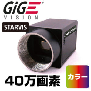
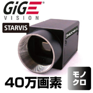
GigE camera
1/1.1 inch
CS1200-GC (12 million pixels, color)/
CS1200-GB (12 million pixels, monochrome)
EG1200-GC (12 million pixels, color)/
EG1200-GB (12 million pixels, monochrome)
1/1.7 inch
CS1200-C (12 million pixels, color)/
CS1200-B (12 million pixels, monochrome)
EG1200-C (12 million pixels, color)/
EG1200-B (12 million pixels, monochrome)
1/1.8 inch
DN3RG-130 (1.3 million pixels, color)/
DN3RG-130BU (1.3 million pixels, monochrome)
DN3RG-200 (2 million pixels, color)/
DN3RG-200BU (2 million pixels, monochrome)
EG320-C (3.2 million pixels, color)/
EG320-B (3.2 million pixels, monochrome)
EG600U-C (6 million pixels, color)/
EG600U-B (6 million pixels, monochrome)
1/2.3 inch
DN3R-1000 (10 million pixels, color)
1/2.5 inch
CS500-C (5 million pixels, color)/
CS500-B (5 million pixels, monochrome)
DN3R-500 (5 million pixels, color)
1/2.9 inch
CS41-C (400,000 pixels, color)/
CS41-B (400,000 pixels, monochrome)
EG41-C (400,000 pixels, color)/
EG41-B (400,000 pixels, monochrome)
1/2 inch
CS130U-C (1.3 million pixels, color)/
CS130U-B (1.3 million pixels, monochrome)
CS500U-GC (5 million pixels, color)/
CS500U-GB (5 million pixels, monochrome)
EG130U-C (1.3 million pixels, color)/
EG130-B (1.3 million pixels, monochrome)
1 inch
CS2000-C (20 million pixels, color)/
CS2000-B (20 million pixels, monochrome)
EG2000-C (20 million pixels, color)/
EG2000-B (20 million pixels, monochrome)
2/3 inch
EG501-C (5 million pixels, color)/
EG500-B (5 million pixels, monochrome)
Summary
The size of the image sensor is information necessary for calculating the field of view and selecting a lens. For CCTV lenses, use the following formula when calculating the lens for the desired vertical field of view:
f value = (distance to object (mm) x vertical size of image sensor (mm)) / vertical field of view
For macro lenses, the size of the image sensor is used to calculate the total magnification that will ultimately be displayed on the monitor.
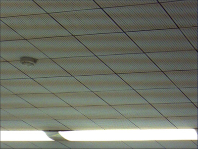
The “flicker phenomenon” refers to a phenomenon in which abnormalities such as “light and dark fluctuations” and “color tone shifts” appear in images captured by a camera, although they cannot be detected with the naked eye.
In this article, we will introduce “What is the Flicker Phenomenon” and “How to Mitigate the Flicker Phenomenon”.
The flicker phenomenon is
Some lighting devices flash to match the power frequency, while others pulse as a dimming system.
Although the flashing of light cannot be felt with the naked eye, if the shutter speed of the camera is faster than the blinking cycle, abnormalities such as “light and dark fluctuations” and “color tone shifts” will occur in the captured image. This is the flicker phenomenon.
The flicker phenomenon occurs under lighting such as fluorescent lamps that emit periodic light, and does not occur under direct current lighting.
There are two main symptoms of flicker.
In a camera with a global shutter system, the entire image periodically repeats fluctuations in brightness.
On the other hand, with a rolling shutter camera, horizontal stripes may appear in the footage, which may appear to flow vertically.
< Flicker Phenomenon: Horizontal Stripes of Light and Dark in Rolling Shutter Cameras>
How to prevent flicker phenomenon
Basically, there are only three ways.
1. Use a direct current lighting system.
2. Set the shutter speed to be slower than the blinking speed.
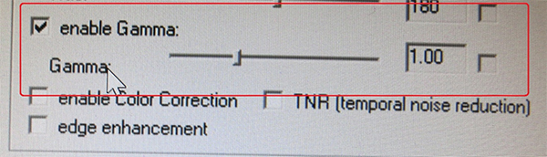
3. Use a camera equipped with a “flicker-free function”.
1. Use a direct current lighting device.
It occurs under lighting that repeatedly emits periodic light, and does not occur in lighting with direct current lighting.
2. Set the shutter speed to be slower than the blinking speed.
The flicker phenomenon can be suppressed to some extent by adjusting the camera’s exposure time or shutter speed, but it cannot be completely eliminated. Even if the flicker seems to disappear, the light and dark are changing over a long period of tens of seconds or more. Especially when using a high-speed camera under fluorescent lighting, a significant flicker phenomenon occurs.
※ If the shutter speed cannot be adjusted on the camera side, the aperture of the lens can be adjusted to compensate for the lack of illumination with DC lighting to reduce the effect of pulse lighting relatively.
3. Use a camera equipped with a “flicker-free function”.
The “flicker-free function” is a function in which the camera automatically detects the flashing of the light source and releases the shutter at a timing that has little effect on the brightness and color tone.
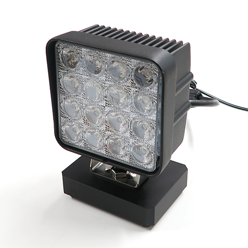
To avoid the flicker phenomenon, use direct current lighting or strobe lighting synchronized with the camera shutter for high-speed camera lighting.
We offer a wide range of high-speed cameras and lighting equipment suitable for those applications, such as high-speed camera lighting and strobe lighting.
If you are suffering from the flicker phenomenon, please feel free to contact us.
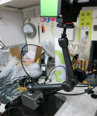
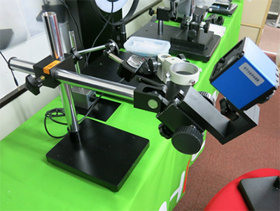
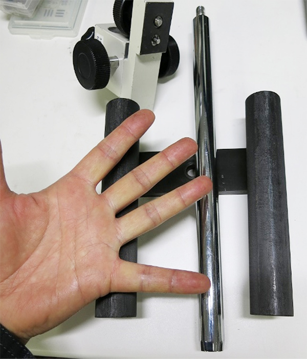
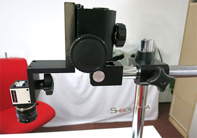
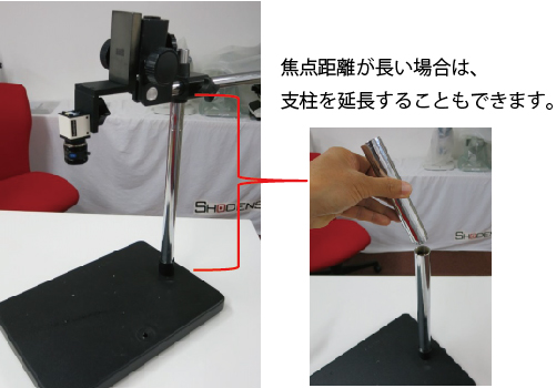
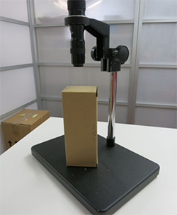
When using a camera with a wide field of view or a long operating distance, the support of the stand may be reflected.
In this case, adding a horizontal stay to a regular camera stand can avoid reflection.
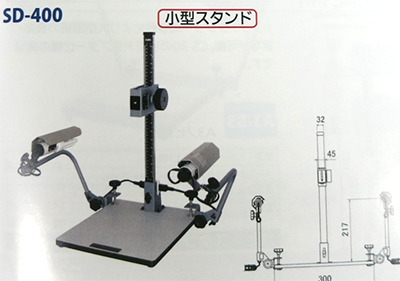
The following camera accessories are also available at camera specialty stores.
If you would like to know more about our products, please contact our technical support.
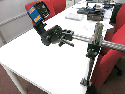
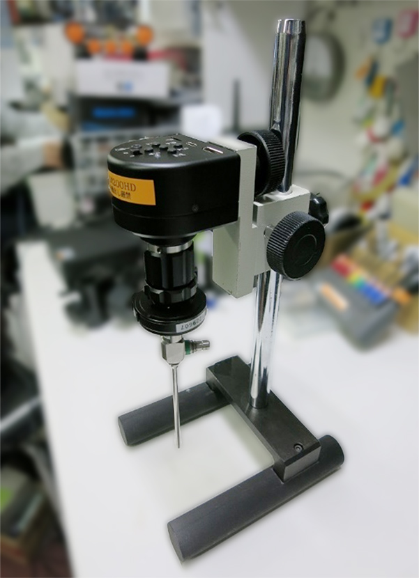
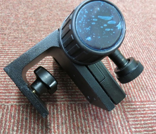
The load capacity of the camera angle attached to the end of the flexible arm (FA100-M) manufactured by Shodensha is 5 kg.
By attaching this to the camera stand, it can be made into a 5 kg load-bearing type.
(A normal camera stand weighs 2 kg.)
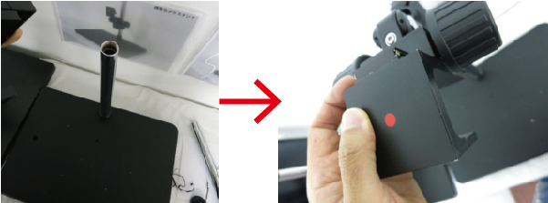
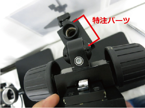
In order to attach the camera angle for flexible arm to a 25mm dia. post, the following parts must be custom-made.
Since they are custom-ordered, the length can be manufactured according to your request.
Production Examples
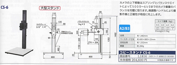
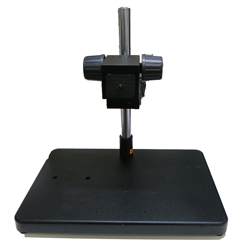
<Camera stand with a load capacity of 5kg
Camera mounting screws are common in most cases.
In many cases, thermographs and large high-speed cameras also share the same mounting screws.
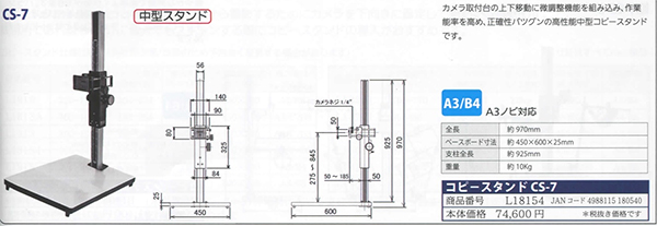
If you are looking for a stand with a high load capacity, you can easily find one by looking for camera supplies.
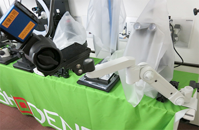
Although dedicated equipment may be available, we will introduce an easier and less expensive way to take pictures.
Load capacity 5kg type
Load capacity 10kg type
Shodensha also has a custom-made camera stand with a load capacity of 5 kg.
How long do you record for? How will it be stored? Is there a need to remotely view Live video? How many cameras are needed? There are various methods depending on the purpose. There are three main methods.
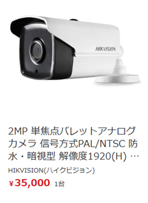
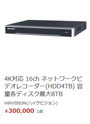
(1)Security camera
A camera and a recorder are required, and the camera and recorder are connected to one network. Videos are stored on the recorder. All necessary videos can be saved as data. Basically, Live video can be checked within the network.
Merit
・Long time recording (e.g. 1 month)
・Multiple cameras (e.g., 16 cameras) can be recorded
・All recorded data can be saved
Demerit
・Wiring and setup are complex (generally done by a professional installer).
・Cameras are relatively inexpensive, but recorders are expensive.
(Recorder prices vary depending on the number of units and capacity of recorders that can be connected.)
・Cameras are often integrated and lenses are not interchangeable.
<Examples of commercially available security cameras and recorders>
(2)Cloud Camera
In this system, you purchase only the camera and pay a monthly fee for cloud usage. Videos are stored on the cloud for a “fixed period of time”. You can watch them as many times as you like within that period. To fully save the video, it must be downloaded, and the downloadable time is determined by the initial contract. You can view the Live video from anywhere with the URL you are given.
Merit
・Very easy to wire and set up
・Long time recording (e.g. 1 month) is possible
・Capable of recording multiple cameras (16 cameras, etc.)
・Viewing is possible from anywhere with an Internet environment
Demerit
・Full storage of recorded data is limited to a certain amount of time
・Lenses cannot be replaced in many integrated cameras
・Security concerns remain
<An example of a commercially available cloud camera>
(3)Industrial Cameras
The camera is not dedicated, but a generic product. It only connects to a PC via LAN or USB and is not connected to a network. Videos are stored on the connected PC or HDD connected to the PC. Live video can be viewed only on the connected PC.
メリット
・Wiring and setup are very easy (software installation only)
・Lens can be replaced with a general-purpose industrial camera (C-mount)
・By adding software, it can be used in other ways (e.g., recording before and after an abnormal event)
・All data is recorded on a PC, so post-processing (editing) of files can be done with a series of PC operations
・Camera can be downsized
デメリット
・The recording time and the number of cameras are limited due to the limited capacity of the PC or HDD.
(Những gì chúng tôi có thể cung cấp là camera 1,3 triệu pixel, có thể kết nối với 8 camera và ghi hình 8 giờ mỗi ngày
trong khoảng 7 ngày)
Industrial cameras and additional software are available from us.
We sometimes receive requests from customers who want to use a USB camera to “capture and store long videos.” We have received requests from our customers to “record and save long videos” with a USB camera.
In this issue, we would like to introduce several methods for recording long videos with a USB camera.
Use Hi TriggerREC, a multifunctional compressed video recording software
Our USB 3.0 cameras offer Hi TriggerREC software, which makes it easy to create long videos.
・Features of Hi TriggerREC
*Video recording in H.264 compressed (.mp4) / uncompressed (.avi) format is possible.
A variety of functions are also included, such as a snapshot function that allows you to take still images at any time, and a versatile recording/stop trigger function that combines an external signal and a timer.
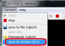
Use the Viewer software that comes standard with USB cameras
Our USB 2.0 cameras can record with the included standard-supplied Viewer software, but the AVI file standard for exporting is outdated and a file size limit of 2 Gbytes exists.
If you need a short time, you can use this Viewer software. (In case of 1.3 megapixel type (1280X1024) at 30 fps, it can record for about 15 seconds.)
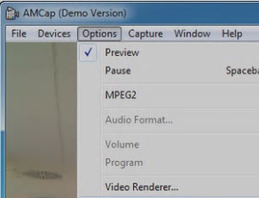
Use commercial or free recording software
Our USB 2.0 cameras can also be used as DirectShow cameras, so basically you can record with commercial or free recording software that supports DirectShow.
If you have such recording software, you can check if it is possible to record using a demo unit on loan. One well-known free software is “Amcap” provided by Microsoft as a sample program.
(The only saving format is uncompressed (AVI).
Use a converter to record for longer periods of time on your computer
Although not a USB camera, there is also a way to attach a USB 3.0 converter to an HDTV and record for long periods of time on a PC.
All of our HDTV models can record video if you use I-O Data Device’s GV-USB3/HD.
There are a few things to keep in mind when using a PC and a USB camera
for long-duration video recording.
1. About Compression
Video data files can be very large.
There are some free video recording software available, but in most cases,
they are uncompressed (AVI files, etc.).
For long time recording, it is necessary to compress the data in H.246 format
or other formats to record for long periods of time.
In the case of 1 hour of recording at 1280 x 1024 (1.3 million pixels) at 30 fps,
the file size is 430 x 430 x 430 pixels (1.3 million pixels) at 30 fps,
・430GB if uncompressed
・If compressed, it will be about 16.5GB.
2.About Playback
It is not a problem for about 24 hours, but be careful when the level reaches 3 days, 1 week, etc.
Even if recording can be done, it may not be possible to play it back with general-purpose playback software
such as Windows Multimedia Player.
For example, if you are recording for a week and each day has 8 hours of recording time,
do not batch record and create multiple files for one day (8 hours).
The compression will be 16.5 GB per hour (1.3 megapixels at 30 fps), which is 130 GB for 8 hours.
A week would be divided into 7 files. 130GB x 7 days = 910GB.
This means that 1TB of HDD can be used for recording. If a file is only 130 GB,
it can be played back with Windows multimedia player, etc.
Trigger control software that is very useful for embedded cameras
Introducing a useful trigger control software that emits a trigger signal from an external source, such as a program controller (PLC) or sequencer, and uses an embedded USB camera.
●Trigger control software type
①Simple is best light model for still image storage with trigger signal input: Hi TriggerF Light
・Our Hi TriggerF Light can save a still image or capture a screen image (temporary storage) at that moment
by inserting an external trigger signal into the camera.
・Live display is also possible without a trigger signal, making positioning and focusing easy.
・A digital zoom function allows you to enlarge or reduce the camera image to the desired size on your PC screen.
It also has a fit-in function that allows the camera image to fit perfectly on your PC screen.
・The exposure time can be adjusted so that even fast objects can be photographed without blurring.
→Perfect for cases where you only need to save still images with external trigger signal input!
②Middle model with still image storage + cross line display, time stamp, and binarization function with trigger signal input: Hi TriggerF Pro
・Our Hi TriggerF Pro adds cross line display, time stamp burning, and binarization to the Hi TriggerF Light functions.
→Perfect for still image storage with external trigger signal input + plus function!
③Hi TriggerF Pro + multifunctional high-end model capable of multiple activation of 4 or 8 cameras: Hi TriggerF PRO4 / PRO8
・Our Hi TriggerF PRO4 / PRO8 can multiplex up to 4 / 8 cameras in addition to the functions of Hi TriggerF Pro.
→Perfect for use with multiple cameras up to 4/8 units!
●Pre-tests and demo equipment are available for use with peace of mind.
・I don’t know if it’s usable.
・Worried about whether it will work
・I want to test it
→Don’t worry. We will lend you a demo unit with camera, lens, lighting, and software.
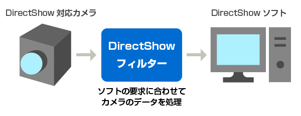
DirectShow is a multimedia framework and API developed by Microsoft.
A DirectShow-enabled camera is a camera that works with the DirectShow framework.
■About DirectShow Filters
The DirectShow filter processes the camera data according to the requirements of the DirectShow software, allowing the camera to be controlled by the software.
The filter matches the camera and software so that they can work together.
Without the filter, the software cannot properly process the data from the camera.
■Major causes of DirectShow-enabled cameras not working with software
There are three main causes of problems:
① If a bug exists that prevents the software from properly utilizing the DirectShow framework.
②When the DirectShow filter is unable to process the data output from the camera according to the specifications required by the software.
③Data from the camera does not match the DirectShow filters supported by the software.
In both cases, correcting the respective causes will improve the situation.
(There are compounding factors, so sometimes everything has to be addressed.)
■Shodensha’s response
If you cannot use commercially available DirectShow software with our DirectShow-enabled camera, we can provide support such as analysis of the cause if you lend us the software. Please feel free to contact us.
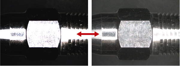
When taking pictures, the camera may make extremely bright areas appear white (halation or blown out highlights), or extremely dark areas may become black and disappear from view (Black Crush).
The range in which the difference in brightness and darkness can be captured at the same time, from one step before halation (overexposure) to one step before blackout (completely dark, unable to see anything), is called the dynamic range. ) is measured.
The wider the dynamic range, the better the camera performance. However, no matter how powerful the camera is, it cannot match the ability of the human eye to capture images. For example, even if a scene is clearly visible to the human eye, when photographed with a camera, it may be overexposed or details may not be visible.
Frame rate refers to the number of frames displayed within a certain amount of time in a video. This number is usually expressed in frames displayed per second and is measured in fps (frames per second).
With USB technology, a theoretical maximum speed is set, regardless of the performance of the computer. Specifically, for USB2.0, the maximum speed is 480Mbps (=60MB/s), and for USB3.0, the maximum speed is 5120Mbps (=640MB/s).
Considering the theoretical performance of a USB camera that uses USB 2.0, it is approximately 15 fps for a 1.3 MP (1280X1024) image, approximately 10 fps for a 2 MP (1600X1200) image, and approximately 10 fps for a 3 MP (2048X1535) image. It is said that it is possible to achieve approximately 6fps. This doesn’t have much to do with camera performance or price.
However, these are only theoretical values, and actual performance may vary significantly depending on CPU processing power, memory capacity, and other system environments (such as software running in the background). In actual measurements, results are often around 60% of the theoretical value or less.
However, there are ways to improve the frame rate slightly. Please contact technical support for more information.
Recently, we have been receiving an increasing number of inquiries about using multiple USB cameras on a single computer at the same time.
I would like to discuss some points to note when constructing it.
●How to connect to a PC
There are two main methods of connecting to a computer.
If your PC has an available PCI-Express slot, you can add an “expansion board” to increase the number of USB ports (connection ports).
One advantage of this method is that one USB port is used per USB camera, so it is less likely to cause problems such as insufficient communication capacity (bandwidth shortage) of the PC or insufficient power supply from the PC to the USB camera due to the increase in data transmission volume caused by using multiple cameras.
This method is recommended when connecting multiple USB cameras at the same time, since it is less likely to cause problems such as insufficient communication capacity (bandwidth shortage) of the PC or insufficient power supply from the PC to the USB camera.
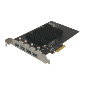
If three or four USB cameras are to be connected at the same time, we further recommend adding an “Industrial Expansion Board”.
The disadvantages are that the board can be added if there is an available PCI-Express slot in that PC, and that it takes more time and effort to add the board.
USB frame grabber board (4 ports)
USB-IB4
The second method is to use a “USB hub” for one USB port on a PC
and connect multiple USB cameras to that USB hub.
One advantage is that it can be done when there is no space in the PC to add an “expansion board”, for example.
It is especially suited for notebook PCs with a small number of USB ports.
Disadvantages include the following.
①Use a USB hub to one USB port on the PC side
Since multiple cameras will be connected, there is a large possibility of “bandwidth shortage,” a shortage of PC communication capacity due to the increase in data transmission volume caused by the use of multiple cameras.。
Compared to adding an expansion board to the desktop to provide additional USB ports, this will further limit the amount of data the camera can use = the number of pixels (resolution) it can use.
②Using a USB hub to connect multiple cameras to a single USB port on the PC side will result in insufficient power supply to the USB camera, which will greatly increase the possibility of not being able to see the image.
The initial setup procedure for recognizing and displaying each camera may become complicated.
③The initial setup procedure for recognizing and displaying each camera may become complicated.
●Software that enables multiple activation (simultaneous use) of multiple USB cameras
Requires software that can be multiply activated on a single PC.
In this issue, we will introduce “Hi TriggerF PRO4 / PRO8,” a highly functional trigger shooting software (multiple-unit version) made by Shodensha.
Advanced Trigger Photography Software (Multiple Units Version)
Hi TriggerF PRO4 / PRO8
Functions of the “Multiple Launch Trigger Software Hi TriggerF PRO4 / PRO8
・Multiple activation is possible for up to 4 or 8 cameras. (Please contact us if you would like more than one camera.)
・Our Hi TriggerF Light can save a still image or capture a screen image (temporary storage) at that moment by inserting an external trigger signal into the camera.
・Live display is also possible without a trigger signal, making positioning and focusing easy.
・A digital zoom function allows you to enlarge or reduce the camera image to the desired size on your PC screen.
It also has a fit-in function that allows the camera image to fit perfectly on your PC screen.
・The exposure time can be adjusted so that even fast objects can be photographed without blurring.
・Cross-line display, timestamp burning, and binarization functions have also been added.
●Available computers
The more cameras you have (3, 4, 8, etc.), the higher spec PCs you will need.
●Other notes
Industrial cameras by themselves do not show anything.
A separate lens is required for each focal length and magnification.
Additional lighting may also be required depending on the brightness of the camera installation location.
→Please contact our technical department if you would like to use multiple USB cameras for multiple activations. We can propose a total system.
When CMOS sensors first began to be used in cameras, the following differences were recognized between them and CCD sensors.
1. CD provides more natural color reproduction.
2. CCD images are clearer.
On the other hand, it has been pointed out that with CMOS sensors, minute blurring occurs in images and the clarity is poor. .
3. The CMOS sensor uses a rolling shutter method, which tends to cause distortion and afterimages in moving scenes.
There was an impression that early CMOS sensors were of low quality, but as technology advances, the performance of CMOS sensors has improved and is now comparable to CCD sensors. Regarding the difference between CCD and CMOS
<CCD is・・・>
1. Occurrence of smear (a phenomenon in which a band of light appears on the image).
2. Often more expensive than CMOS.
3. Power consumption is higher than CMOS sensors, making them unsuitable for battery-powered digital cameras and video cameras.
4. Because it is not possible to read out only a portion of the image sensor, it is difficult to lower the resolution and increase the frame rate.
<CMOS is・・・>
1. CMOS sensors have an amplifier built into each pixel, which tends to cause certain pattern noise due to variations in performance.
2. The production process for CMOS sensors is similar to that for CPUs and LSIs, and they can be manufactured at lower costs than CCD sensors.
3. CMOS sensors can be operated at lower voltages, which facilitates faster data readout and higher resolution.
4. Because partial readouts are possible, cameras using CMOS sensors can improve frame rates by lowering the resolution.
CCD sensors suffer from smearing, while pattern noise is a major problem with CMOS sensors. However, with improvements in manufacturing technology and noise correction, pattern noise in CMOS sensors is gradually becoming less noticeable.
Also,
CMOS → Rolling shutter → Sensitive to movement
CCD → Global shutter → Strong against movement
Although there was a relationship that was sometimes expressed as “CMOS sensors”, CMOS sensors with global shutters are now being produced.
In the past, CCD was the main focus in device development, but today CMOS has become mainstream, and technological advances are supporting improvements in CMOS performance.
As a result, the idea that CCD is superior to CMOS is no longer universally applicable; image quality and performance vary depending on the type of sensor.
As a result of sensor manufacturers, particularly Sony, discontinuing the production of CCDs, the switch to CMOS is accelerating in fields that traditionally used CCDs.
Shodensha provides cameras equipped with CMOS sensors with global shutter functionality, and supports the smooth transition from CCD to CMOS.
The competitive price of CMOS sensors directly contributes to lower operating costs.
Summary
1. CCD sensors are said to have the ability to reproduce more natural colors.
2. The image provided by CCD sensor is clearer. On the other hand, images from CMOS sensors may have minute blurring, which affects the clarity of the image quality.
3. Since the CMOS sensor is based on a rolling shutter method, it has been evaluated as being vulnerable to capturing moving scenes.
However, over time, CMOS technology has improved significantly and now it is comparable to CCD sensors. Therefore, the general idea that CCD is superior to CMOS no longer applies universally, and differences in image quality and performance now depend on the unique characteristics of each sensor. Additionally, CMOS sensors equipped with a global shutter are currently being produced.
Shodensha Global Shutter CMOS camera lineup
USB3 Vision camera (USB3.0, 1.3 MP, color) CS130U-C
DirectShow refers to a set of instructions, functions, and norms developed by Microsoft that apply to libraries and programs for video conversion. Quite simply, a DirectShow-enabled camera can be programmatically controlled using common instructions.
This mechanism allows the user to operate the camera through various application software without having to use a dedicated application that comes with the camera when the USB camera is recognized by a PC. However, you may need to take steps to get your PC to recognize the camera, if necessary.
This makes it possible to use a variety of application software from different developers. For example, it is possible to select and use the necessary software according to the application, such as viewer software that simply displays images, software that performs image measurement, software that performs automatic visual inspection, and software that performs 3D image synthesis. There are many companies on the market that only offer software.
However, there are multiple types of video formats that the camera outputs, and the application software used must support these formats.
Video formats include YUY2, RGB24, and RAW16, for example. While the software provided on its own often supports these common video formats, some software shipped with the camera only supports specific camera-specific formats.
USB Video Class (UVC) is a generic standard name for camera devices connected via USB. Current Linux and Windows systems already include drivers for UVC, so no additional driver installation is required.
This also refers to these cameras as installation-free cameras or driver-free cameras.
In contrast, many industrial cameras require manufacturer-specific drivers, which require the application to install driver software separately.
Below is a list of advantages and disadvantages of UVC cameras.
■ Features of UVC Camera
<Advantages of UVC cameras>
(1) On Linux and Windows, even between different camera brands, if you use a UVC camera, you can program with almost the same coding.
This eliminates the need to learn the SDK for each camera brand separately.
(2) There are very affordable models of UVC cameras, which make it possible to build a system at a low cost.
(3) In both Linux and Windows environments, you can easily acquire video using the VideoCapture class of OpenCV (OpenCV Sharp, OpenCV-Python).
<Disadvantages of UVC cameras>
(1) There are few UVC cameras that support external triggering, because the UVC standard does not take into account shooting with external triggers. This is especially true when you want to shoot with a signal from an external PLC (sequencer) or sensor.
*Shodensha has added a UVC camera that can be connected to an external trigger to its lineup. Please contact us for more information.
(2) For most UVC cameras, even if you set detailed settings such as brightness, color, and shutter speed, these settings will be reset when the power is turned off.
Therefore, these settings must be recorded separately by the program and reapplied when the camera restarts.
In contrast, many industrial cameras allow you to save the settings in the camera, and even after the power is turned off, it automatically returns to the previous settings when the power is switched back on.
*Shodensha offers a special UVC camera that allows users to precisely adjust and store the white balance. Please contact us for more information.
(3) UVC cameras have the advantage of being able to easily acquire images using OpenCV, but the current OpenCV (as of version 4.5.2) does not have a function to fine-tune the white balance.
This can be a major barrier, especially in tonal applications.
This is not a limitation of the UVC camera itself, but a problem caused by the lack of functionality of OpenCV.
*In order to meet these needs, Shodensha provides UVC cameras that can finely adjust the white balance and save the settings. Please contact us for more information.
(4) When multiple UVC cameras are used on one PC at the same time, it is possible to obtain the image output from each camera, but since it is not possible to distinguish between individual cameras, the image display position may change every time the PC is restarted.
For this reason, if you are considering the simultaneous use of several cameras, we recommend that you use a regular industrial camera.
■ Shodensha’s UVC camera
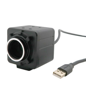
C-mount type low-cost UVC camera series (WA2 series)
There is no external trigger terminal, and although you can adjust brightness, color, and shutter speed using the Viewer software, these settings are reset when the power is turned off. This series is a cost-conscious choice.
C-mount type industrial UVC camera series (DN series)
It is equipped with an external trigger terminal and includes a tool program that allows detailed white balance settings and their storage using OpenCV.
This series has features that compensate for the typical limitations of UVC cameras and is designed for industrial applications.
C-mount type low-priced UVC camera series (WA2 series)
C-mount type industrial UVC camera series (DN series)
Summary
VC cameras are also called “driver-free cameras” or “installation-free cameras” because they utilize drivers built into the operating system. Its main advantage is ease of implementation.
However, on the other hand, there are drawbacks such as “the white balance cannot be adjusted and saved” and “it does not support external trigger signals.”
Shodensha offers UVC cameras that solve these problems. Please feel free to visit our homepage.
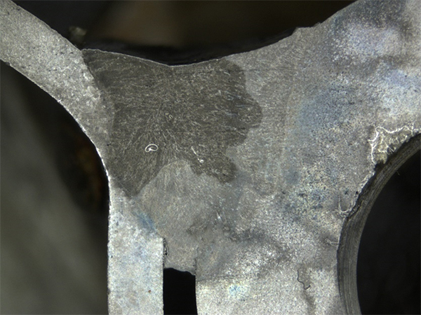
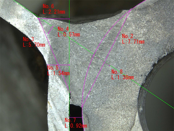
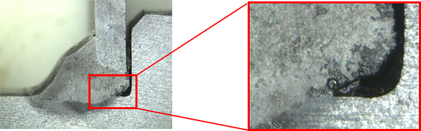
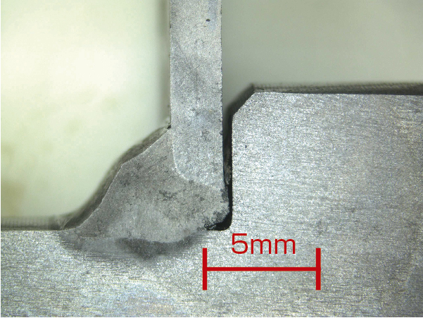
Welding is an important means of bonding metals, and the weld part is very important because it is directly related to the safety of the product.
Therefore, the amount of penetration of the weld is inspected, i.e. dimensional measurements are taken to confirm the depth and quality of penetration. Identify problems such as insufficient penetration, incomplete weld fusion, gaps, and excessive swelling.
<Preprocessing>
In order to properly inspect the penetration in the cross-section of the weld, the following pre-treatment is required:
① Cutting the test part
② Polishing the cross-section
③ Etching treatment with chemicals or electrolysis according to the material
After these pre-treatments, observations and dimensional measurements are carried out. These preparatory tasks are often entrusted to specialists, but this time we will present a product that specializes in dimensional measurement of the amount of penetration of welds.
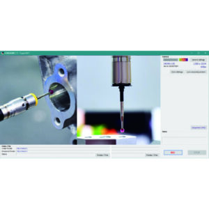
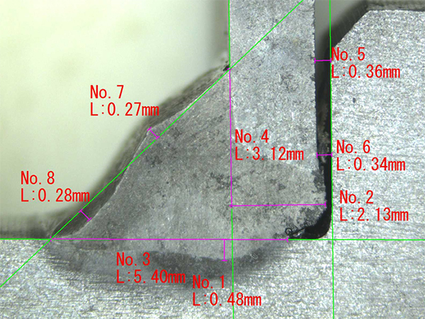
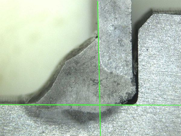
<Imaging and Dimension Measurement>
Specifically, we used our microscope to capture and dimension measurements.
In this process, you need to repeat the following steps:
● Generate a reference line
● Measure the distance from the intersection of the reference lines
●Generate parallel lines
● Measure the vertical distance from the reference line
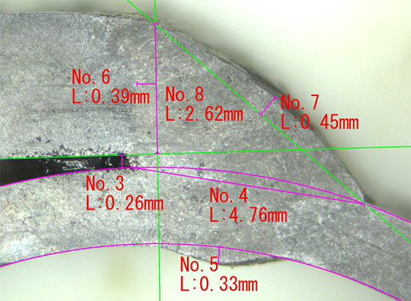
When dealing with a large number of specimens, this task can be quite time-consuming.
However, when using our measurement software, the following measurement support functions are enhanced, and it is possible to improve the efficiency of the time-consuming measurement work of the amount of weld penetration.
<Functions of the measurement software used in this study>
① Occurrence of cross lines
By clicking the mouse on the screen, a cross line will appear at any position.
If the position is misaligned, you can easily repeat the click to adjust the position.
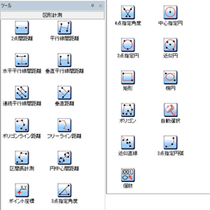
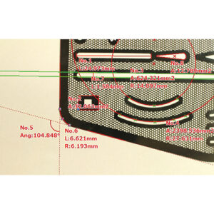
② Abundant measurement items
It is equipped with a wide range of measurement functions and can be used not only for measurement tasks, but also as a reference line.
In this case, you can set the display of the measured value to be hidden.
This feature is particularly useful for measuring “vertical distances”.
In addition, the display color of each measuring line or numerical value can be changed individually.
● Distance between two points
● Distance between parallel lines
● Horizontal parallel distance
● Vertical parallel line distance
● Vertical distance
● Distance between the centers of the circle
● Point coordinates
● 3 point specified angle
● 4 points specified angle
● 3 points designated circle
● Approximate circle
●Rectangle
● Ellipse
● Approximate straight line
●Three-point arc etc
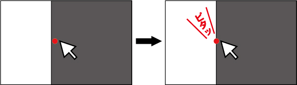
③ Edge auto-fit function
When the mouse cursor is brought close to the desired measurement line, edge detection is automatically performed and the cursor fits the line.
This minimizes errors during the measurement process and results in more accurate measurements.
④ Pinpoint digital zoom function
You can use the mouse wheel to digitally zoom around the position that the cursor is pointing to.
This allows for intuitive scaling and further reduction of measurement errors.
⑤ Scale display
You can display the scale at any position at the desired size.
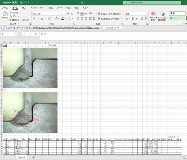
⑥ One-click one-shot reporting function
Simply click the Print to Excel button to transfer the measurement data to Excel. This makes it easier to process data and create charts in Excel, which helps reduce reporting time.
It is very convenient to output raw images, images with measured values, and measurement values to Excel at once.
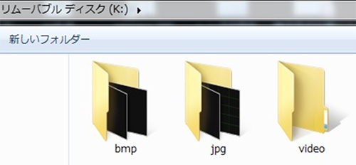
Our GRAV-1 video recorder offers the ability to store video data using a USB memory.
The device supports USB flash drives with a capacity of up to 32 GB and uses FAT32 format. It is possible to save image files in JPEG or BITMAP format. Especially in the case of jpeg format, the file size per sheet is about 100 KB.
Theoretically, up to 320,000 images can be stored.
However, the FAT32 format has a limit on the number of files, and the maximum number of files that can be stored in the root directory is about 65,000.
As a result, even if there is plenty of space, the number of images that can be stored is limited to 65,000.
To deal with this problem, the GR-AV1 automatically creates three folders and stores files in these folders in order.
However, it is not possible to change the directory structure, and therefore will continue to be affected by the file limit described above.
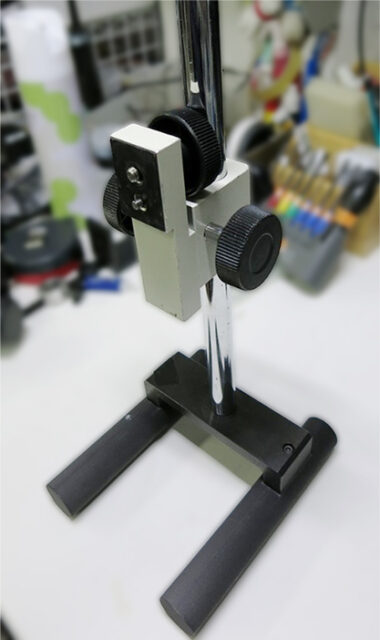
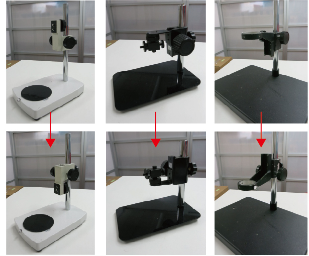
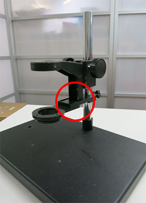
When using a stand, you may find yourself in a situation where you want to adjust the distance to the object you are observing. This refers to when you want to get closer to an object or conversely, when you want to keep a distance. In addition, if you are wearing other accessories, these may interfere with each other.
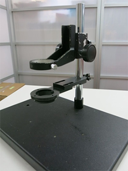
In fact, on a large number of stands, it is possible to mount the angles upside down. (Of course, the stand provided by our company can also be mounted upside down.)
■ Useful when interference with other accessories is a problem.
Reversing the angle may solve the interference problem.
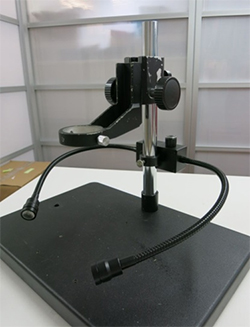
Example of using a standard stand (GR-STD4) and an LED angle (LED-A2)
Example of using a standard stand (GR-STD4) and flexible LED spot lighting (SPF-FL3)
■ This method is also useful if you need to adjust the position of the lens depending on what you are observing.
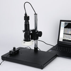
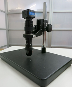
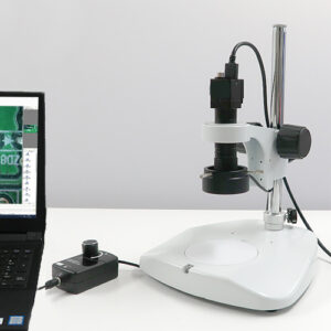
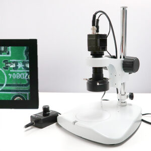
If you are looking for an affordable and relatively advanced microscope, we recommend the DS-PC4 (USB microscope) and DS-70TV4 (video microscope). These microscopes have limited zoom capabilities and do not allow the use of auxiliary lenses, but they are a very cost-effective option if they meet your requirements.
In particular, the DS-70TV4 is a great help because it can be carried with a portable video recorder with a monitor to perform observation tasks anywhere.