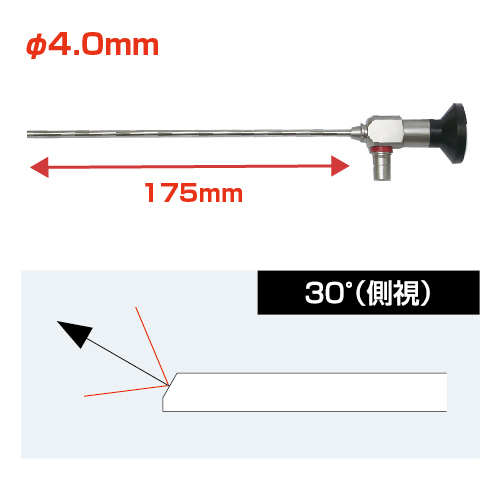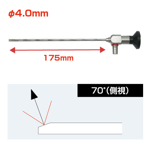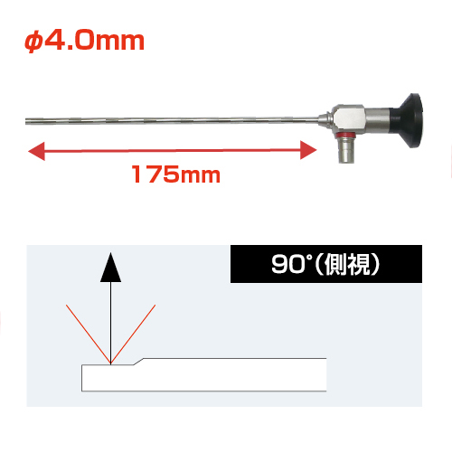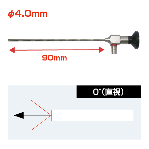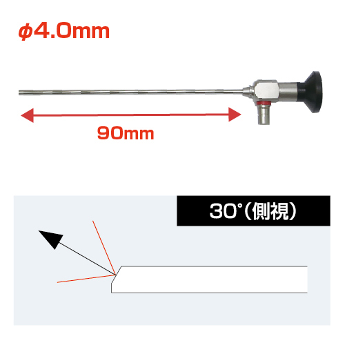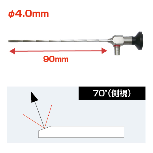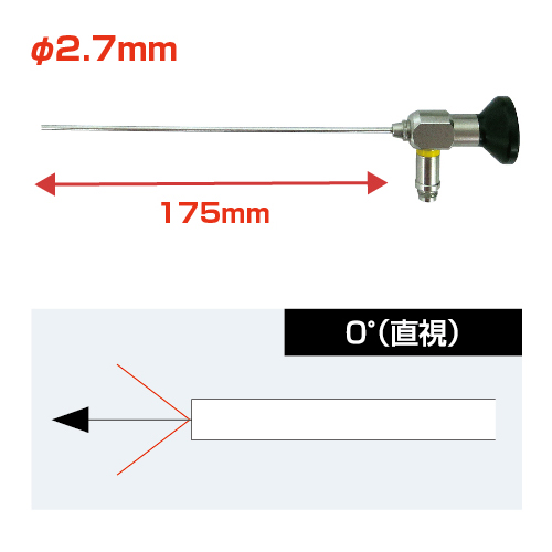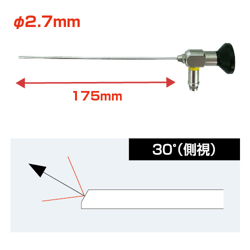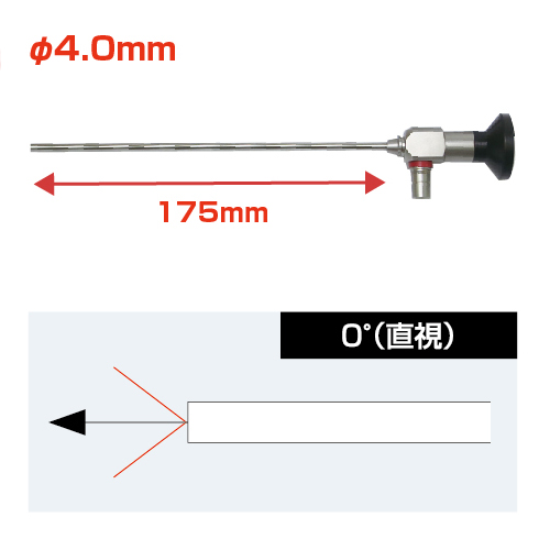
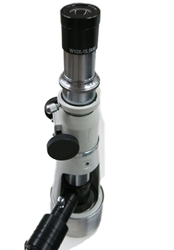
Low cost borescope
Available to observe narrow space
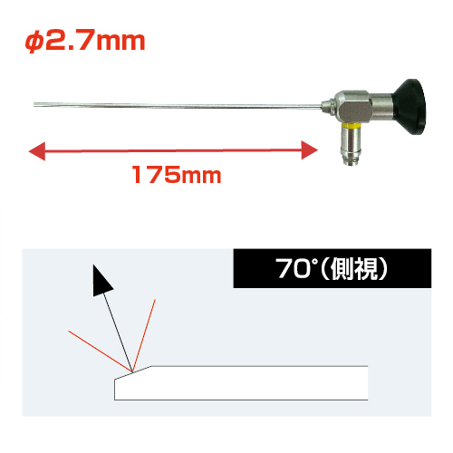
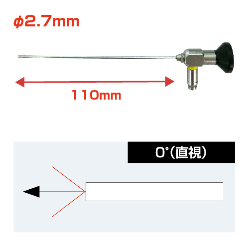
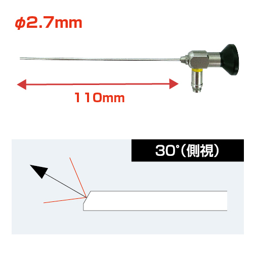
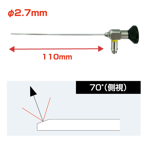
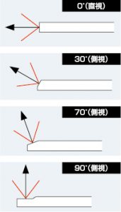
- You can visually inspect nondestructively the inside of a narrow space where human eyes can not reach directly.
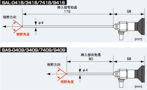
- Field of view angle
0°(Direct)
Available to observe narrow space
Available to observe narrow space
Available to observe narrow space
Available to observe narrow space
Available to observe narrow space
Available to observe narrow space
Available to observe narrow space
Available to observe narrow space
Available to observe narrow space
Available to observe narrow space
Available to observe narrow space
Available to observe narrow space
Available to observe narrow space
When observing with a binocular stereomicroscope with both eyes, the objective lens is slightly oblique so that the object is close to the actual view.
(It is the same as looking at nearby objects with both eyes of a human.)
Therefore, looking at the following objects with one eye
 |
 |
You can see the side slightly. (In other words, you will be looking at diagonal.)
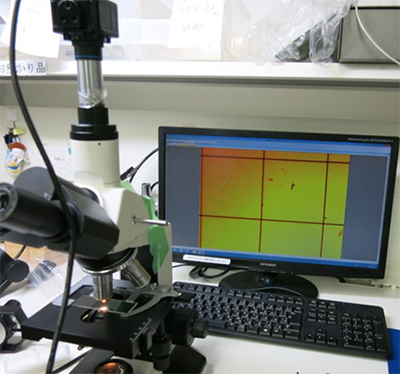
When the microscope is moved up and down, the field of view also shifts slightly.
The focus synthesis software is made on the premise that the field of view does not shift.
(It is assumed that it vertically moves up and down to the object)
If you use focus synthesis software with a stereomicroscope, it will blur like a photo below.
Mitani Shoji’s focal synthesis software (WinROOF 2018 Lite) has “microscope mode”.
Focus synthesis is possible without bleeding by focus synthesis using this function.
We also support these problems. Please feel free to contact us.
 |
Of course, if you are a straight tube microscope like the one on the left, you can use normal focus synthesis software without problems. |
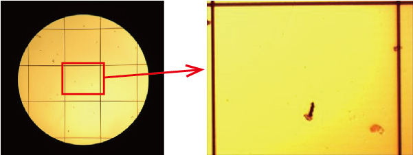
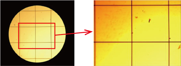
When you observe the microscope with the naked eye, the field of view gets rounded.
(We are using glass scales in increments of 0.5 mm as test samples.)
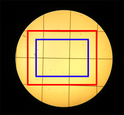
When this is shot with a camera, it becomes a 4: 3 rectangle with enlarger size.
Besides that, the field of view will change depend on the magnification of the camera connection (connector lens), the size of the image sensor of the camera, and so on. (It will also be a red field of view and a blue field of view in combination.)
You can express this with monitor magnification. (You can also calculate.)
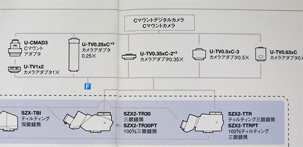
■Camera connection part is C-mount
If the camera connection part on the microscope is C mount, the C mount part also has magnification.
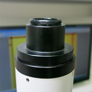
If you do not specify microscope, it seems that a C mount adapter of equal magnification (1 times) is often attached.
Monitor magnification = magnification of objective lens × magnification of C mount × (diagonal length of monitor / diagonal length of camera sensor angel)
1 / 2.5 inch camera (diagonal length of camera sensor angel is 7 mm)
19 inch monitor (diagonal angel 470 mm),
C mount part (equal magnification),
Objective lens 10 times
<Magnification caculation>
10 times X 1 times X (470 mm / 7 mm) = 670 times
The field of view will be like the bottom picture.
Since the horizontal dimension of the 19 inch monitor is 370 mm. So, the image on the right spreads to the screen
<Measured magnification>
370 / 0.55 mm = 672 times
Magnification caculation (monitor magnification) and actual magnification are the same.
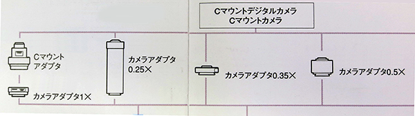
We need to reduce the magnification of C-mount in order to increase the field of view
We also offer equal size (standard equipment) and 0.5 times (option).
There are various magnifications when looking at other company’s catalogs.
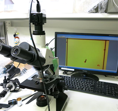
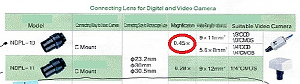
■If you are connected to microscope by JIS len, the magnification can not be changed (equal magnification)
If you are connected a camera to this lens barrel, a relay lens is attached to the camera side. There is magnification in this relay lens.
Magnification calculation is as follows:
Monitor magnification = magnification of the objective lens × magnification of the connector lens × (diagonal length of monitor / diagonal length of camera sensor angle)
1 / 2.5 inch camera (image sensor diagonal 7 mm),
19 inch monitor (diagonal 470 mm)
Connector lens (0.45 times),
Objective lens 10 times
<Calculation magnification>
10 times X 0.45 times X (470 mm / 7 mm) = 302 times
Since the horizontal dimension of the 19 inch monitor is 370 mm. So, the picture on the right spreads to the screen then:
<Measured magnification>
370 / 1.2 mm = 308 times
Magnification caculation (based on magnification on monitor) and actual magnification are the same.
Our company has 0.45 times and 0.37 times connector lens available.
We’ll advise the suitable one to the customer according to the size of the image sensor of the camera.
The magnification of the optical microscope and the magnification of digital microscope are very different.
The magnification of optical microscope is absolute magnification, even if the manufacturer differs, if the magnification is the same, it will be in the same field of view. (It is an absolute magnification.)
However, for digital microscope, the field of view will be very different depending on the manufacturer even at the same magnification. (Relative magnification.)
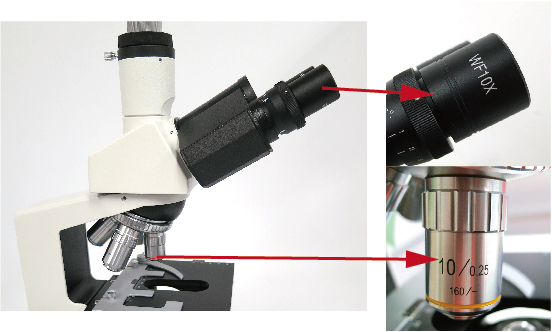
■Optical Microscope magnification
The magnification of the microscope is calculated by the following formula.
Optical magnification = (magnification of the objective lens) × (magnification of the eyepiece) Magnification of the microscope = optical magnification.
(In the case of the microscope of the bottom photograph, the magnification becomes 10 times the magnification of the objective lens × the magnification of the eyepiece 10 times, the optical magnification becomes 100 times.)
Even in the case of a microscope, when the camera is attached to microscope, it may be expressed including the monitor magnification.
(Refer to “How to calculate magnification of camera for microscope”.)
■Digital Microscope magnification
Taking an example of a microscope with an objective lens, which is easy to understand.
Firstly, the calculation of optical magnification is the same as the microscope.
Optical magnification = (magnification of the objective lens) × (magnification of the lens)
(In the microscope of the below picture, the magnification of the objective lens is 10 × magnification × 2 times the magnification of the lens body, the optical magnification is “20 times.”)
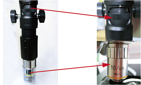
However, the monitor magnification is shown here.
Overall magnification = monitor magnification × optical magnification.
If the image sensor size is 1/2 inch and the monitor is 17 inches, the monitor magnification is 54.
(Please refer to “magnification of microscope”.)
Overall magnification = monitor magnification × optical magnification = 54 × 20 = 1080 times.
In conclusion, if the monitor size or image sensor size changes, the magnification will also change.
(Looking at the catalog of each manufacturer, there is a note such as “Equivalent to” ○○ inches monitor “
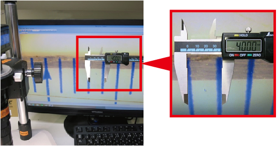
< Magnification definition>
Computing is complex, but the way of thinking is simple.
Microscope as shown below with 1mm on the display to 40mm.
This is simply 40 times.
The magnification concepts of a microscope and a macro lens are different and not interchangeable.
The magnification of a microscope is calculated as:
Optical Magnification = (Objective Lens Magnification) × (Eyepiece Lens Magnification).
The magnification of a macro lens is calculated as:
Optical Magnification = (Objective Lens Magnification) × (Lens Body Magnification).
In the case of a microscope, the overall magnification includes the consideration of monitor magnification in addition to the optical magnification.
Total Magnification = Monitor Magnification × Optical Magnification.
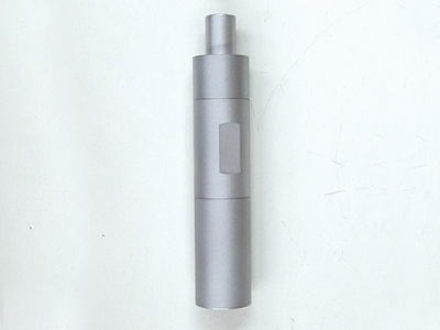
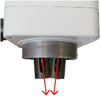
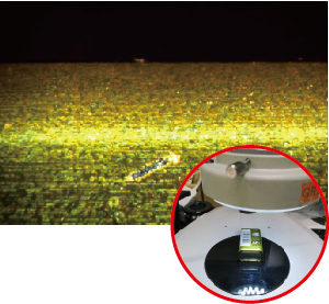
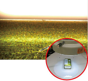
Various bore scope of, fiber scope which size is M10, P = 0.5 can be mounted to this handy type of LED lighting.
A Lithium battery comes as standard accessory.
※Charger is optional parts.
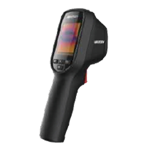
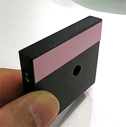
●Without a laser pointer, you can safely measure body temperature.
●Inspection can be performed more than 1m away.
●It is set in a narrow range of 30 ° C to 45 ° C for body temperature measurement and can measure with high accuracy of ± 0.5 ° C
●You can quickly measure body temperature in real time.
※60 people can be inspected in 1 minute.
※This thermography is not a medical device.
Features
●Resolution:160×120
●Thermographic accuracy:±0.5℃
●2.4 inch LCD display with 320 x 240 resolution
●Built-in rechargeable lithium battery
●Can be used continuously for up to 8 hours
Function
Thermography: Real-time temperature detection and display on the screen.
Save: Equipped with a MicroSD card for saving captured images.
Shodensha Vietnam is pleased to announce our schedule of Tet Holiday as follow:
– Our office will be closed from Thursday, 23rd January 2020 to Sunday, 02nd February 2020
– Business operation will resume as normal on Monday, 03rd February 2020
We would like to take this opportunity to thank you for your continuous support.
Shodensha Vietnam is pleased to announce our schedule of New Year Holiday as follow:
– Our office will be closed from Saturday, 28th December 2019 to Wednesday, 01st January 2020
– Business operation will resume as normal on Thursday, 02nd January 2020
We would like to take this opportunity to thank you for your continuous support.
We would like to inform you that as of June 3, 2019,
our Hanoi branch will open to the following location:
Hanoi office:
< English >
No.202, Y2 Building, HH04 Block, Viet Hung Urban Area, Giang Bien Ward, Long Bien District, Ha Noi City
< Vietnamese >
Phòng 202, Tòa nhà Y2, Khu HH04, Đô thị Việt Hưng, Phường Giang Biên, Quận Long Biên, TP. Hà Nội
TEL: +84(24)3200-3790
We would like to inform you that as of May 2, 2019, our office will move to the following location:
New address:
<English>
5 Floor, 178/8 Nguyen Van Thuong Street, Ward 25, Binh Thanh District, Ho Chi Minh City
<Vietnamese>
Lầu 5, 178/8 Nguyễn Văn Thương, Phường 25, Quận Bình Thạnh, TP. Hồ Chí Minh
TEL: +84(28)3911-2006 FAX: +84(28)3911-2007 (unchanged)
We are sorry for the inconvenience this may cause you, and your understanding and cooperation are appreciated.
Shodensha Vietnam is pleased to announce our schedule of Tet Holiday as follow:
– Our office will be closed from Saturday, 02nd February 2019 to Sunday, 10th February 2019
– Business operation will resume as normal on Monday, 11th February 2019
We would like to take this opportunity to thank you for your continuous support.
Shodensha Vietnam is pleased to announce our schedule of New Year Holiday as follow:
– Our office will be closed from Saturday, 29th December 2018 to Tuesday, 01st January 2019
– Business operation will resume as normal on Wednesday, 02nd January 2019
We would like to take this opportunity to thank you for your continuous support.
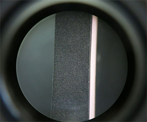
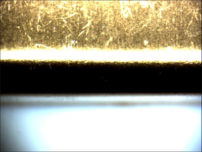
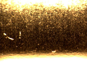
■ Direct Observation of the Cuticle
Even when observing hair at higher magnification, the cuticle might still be difficult to discern. It tends to appear merely as an enlargement of dark particles.
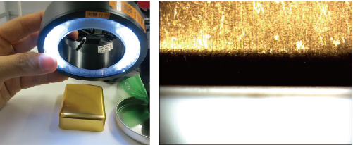
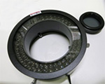
Observation with Ring Illumination
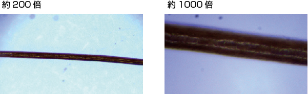
When using ring illumination, particularly with a “coaxial illumination high-magnification type,” visibility might improve slightly. However, it would also require higher lens resolution.
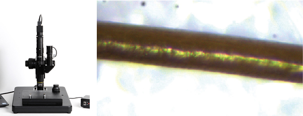
Observation with Metallographic Microscope GR3400J
To capture images like those shown below, an electron microscope would be necessary, which typically costs at least 6 million yen or more. (Note: We do not handle electron microscopes.)
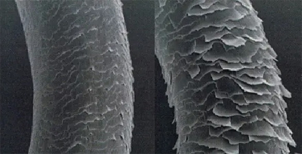
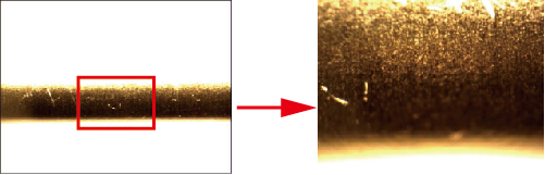
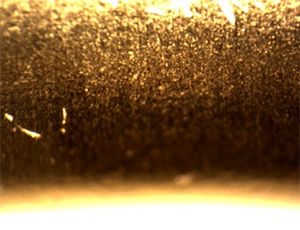
■ Cuticle Observation Image Comparison
Ultra-High Magnification Microscope (USH3130CS-H1) at 800x magnification
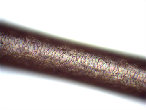
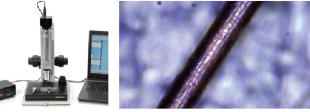
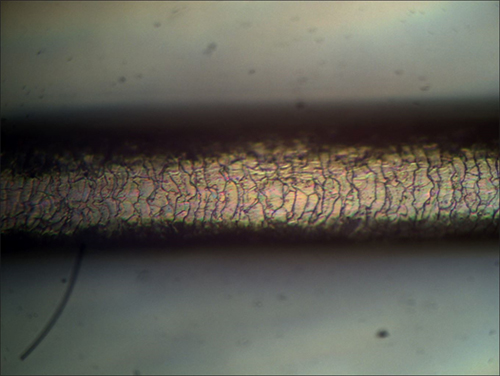
■ Indirect Observation of the Cuticle
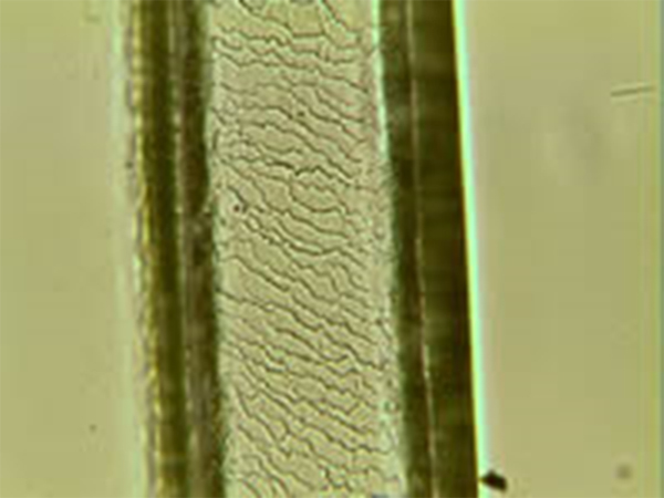
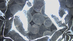
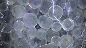
Directly observing the cuticle using a biological microscope is not possible. However, utilizing the “Swamp Method” allows for indirect observation.
Prepare a “Swamp Solution” and a “Swamp Board.”
Place the hair on the Swamp Board, apply the Swamp Solution, and let it sit. The surface of the hair will transfer onto the Swamp Board.
Observation with a Biological Microscope
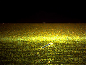
Below are photos taken by our company using the Swamp Method for cuticle observation.
There are the following ways to observe the cuticle.
1. Observation with transmission method using microscope and sump method
2. Observation with metal microscope
1. Observation with transmission method using microscope and sump method
In the case of hair, observing with a microscope will make it appear as a black bar even if you increase the magnification.
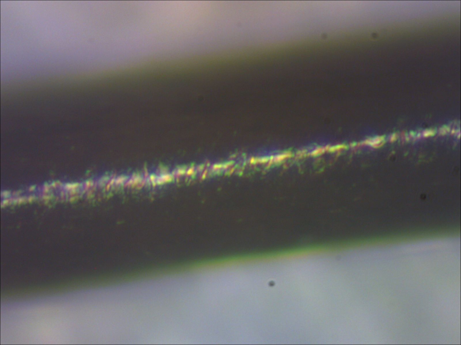 |
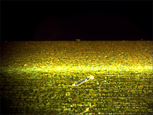
Super High magnification USB microscope SH350PC-2R Observe at 600 times |
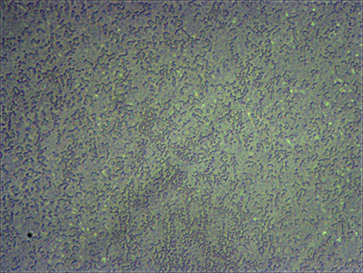
So I will introduce the SUMP.
<What is the Suzuki’s Universal Micro-Printing Method? >
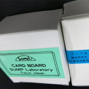
There is a method called “SUMP ※1)」that takes out the shape of the surface of what you want to observe to a very fine part so as to take a mold and observes the thing you copied. It is ideal for observing objects that are impermeable to light, such as plant stem pores and hair cuticles.
* 1 You should buy a set of Sump Sump · Sump Paper · Sump Paperboard at the physical and chemical trading companies.
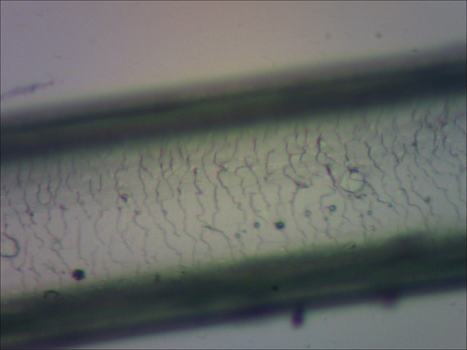 |
Super High magnification USB microscope SH350PC-2R Observe at 600 times Observation with transmission illumination method using the Sump method |
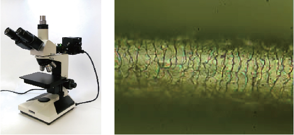
2.Observation with metal microscope
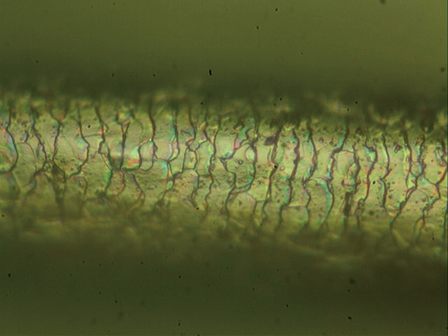 |
GR 3400 J (Metallurgical Microscope) HDCE-30B2 (USB Camera for 3 Megapixel Microscope) A photographed image at 400 times magnification when viewing naked eyes |
Even with a metallurgical microscope it is possible to see the hair cuticle.
However, the size of the metal microscope is as large as 203 x 255 x 421 (H) mm.
How they look depends on models and methods, please contact Technical Support for details.
Some USB cameras themselves have edge emphasis function, but this time we will introduce image processing method.
There is a technique called Unsharp Mask (USM).
There are also functions in PhotoShop etc., but other software also has this function installed.
USM is a type of filter that emphasizes color differences between pixels that make up an image.
Image before unsharp mask is applied
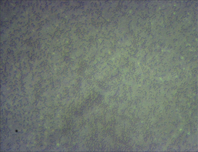
Image after unsharp mask is applied
Sharpen the image that makes you feel blurry in the whole.
It has a function to highlight the outline of the image.
Observing the red circle with normal ring illumination makes the difference between halation and shadow large and very difficult to observe.
Halation can be suppressed by using quadrant LED ring lighting and lighting only in the longitudinal direction.
|
if the light intensity is increased, Observation of R part becomes possible. |
If you increase the magnification as it is, It makes observation of R part easier |
 |
|
| Using a diaphragm lens further increases the depth of focus and makes observation easier. | |
| <Open the aperture> | <Close the aperture> |
 |
 |
However, if you use a diaphragm, it will become darker and the resolution will be slightly lower. So, our lens will be in the practical range up to about 120 times.
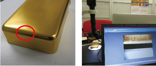
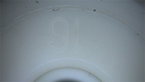
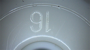
When R is attached to the edge of a workpiece, it may not be seen clearly.
You can see clearly by devising magnification, lighting, background.
| I tried to observe the edge of dry cell | 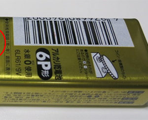 |
|
1. Difference in depth of focus (compare at 80 times) |
|
| Open the aperture | Close the aperture |
 |
 |
| If you open the aperture, the depth of focus will become shallow and the edge may become blurred. | |
| 2.Difference in background color (compare at 80 times) | |
| When the background color is black | When the background color is white |
 |
 |
| The edge may be blurred due to reflection of the background, reflection of the edge part due to lighting, shadows. | |
| 3. Difference in magnification | |
| The depth of focus also varies depending on the magnification. (open the aperture and compare) | |
| at 30 times | at 80 times |
 |
 |
| Even with the same object, the edge may become unclear if the magnification increases. | |
I will show two examples that can suppress halation.
By using two polarizing filters, halation can be suppressed. (For details, please refer to “Polarization observation”.) In case |
|
|
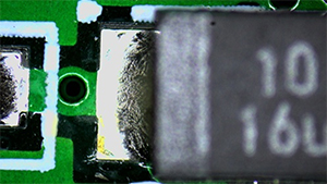
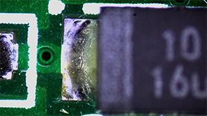
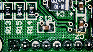
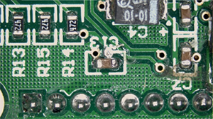
<Actual example when polarization is actually applied 1 Solder of substrate> It can suppress reflection of solder. |
|
 |
 |
| <Before suppression of halation> | <After suppression of halation> |
|
<Example 2 film in the case of actually applying polarized light> The reflection on the film disappeared. |
|
 |
 |
| <Before suppression of halation> | <After suppression of halation> |
|
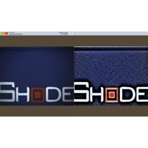
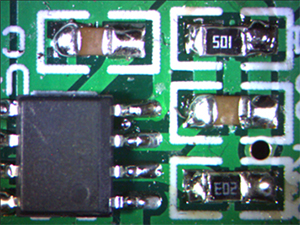
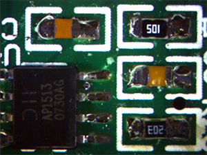
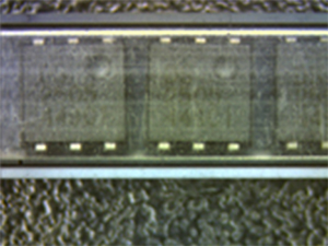
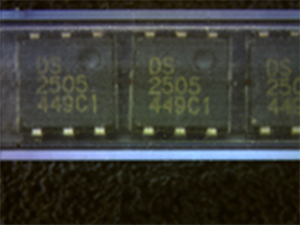
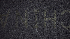
<Actual example when polarized light is applied 3 Stick for IC storage> It is now possible to suppress the reflection of the surface of IC storage sticks and to read IC characters. |
|
 |
 |
| <Before suppression of halation> | <After suppression of halation> |
| <Actual example when polarized light is actually applied 4 IC printing> | |
 |
 |
| <Before suppression of halation> | <After suppression of halation> |
|
<Actual example when polarized light is actually applied 5 Solder part> |
|
 |
 |
| <Before suppression of halation> | <After suppression of halation> |
|
<Example 6 in the case of actually applying polarized light 6 Object in which high reflectance part and low reflectance part coexist> |
|
 |
 |
| <Before suppression of halation> | <After suppression of halation> |
| <Actual Example of Actual Polarization 7 Printing on Film> | |
 |
 |
| <Before suppression of halation> | <After suppression of halation> |
| <Actual example when polarized light is actually applied 8 Object in a plastic bag> | |
 |
 |
| <Before suppression of halation> | <After suppression of halation> |
| <Actual example when polarized light is applied 9 Convex character of white resin (embossed part)> | |
 |
 |
| <Before suppression of halation> | <After suppression of halation> |
|
2. High dynamic range function (HDR function) This is a technique to expand the range of sensor operation at the expense of contrast. Our C mount camera is installed in high definition camera and PC monitor direct camera. |
|
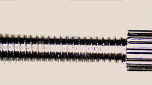
| <Actual example when polarized light actually applied 4 Axis of screw> | |
 |
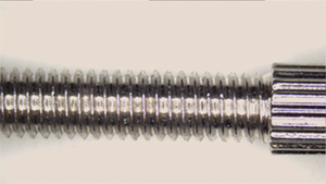 |
| <Shooting in normal mode> | <Shooting in HDR mode> |
 |
 |
| <Shooting in normal mode> | <Shooting in HDR mode> |
We will propose a method suitable for your use. Please contact technical support for details.
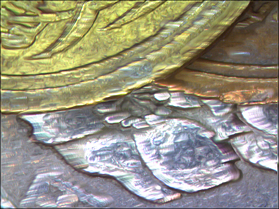
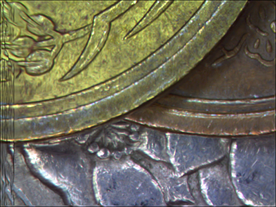
There is a great difference between the part with a white streak and the part of a shadow in the metal processed article, the polished surface and the plated surface are especially innovative.
It is even more difficult if there are convex surface.
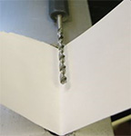
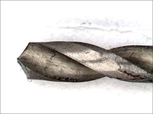
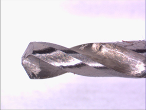
As one example, we confirmed the difference in appearance by changing (1) lighting, (2) camera, (3) background color, and (4) option for the cutting edge of the drill
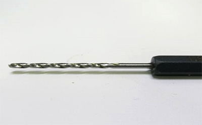 |
Drill cutting edge of φ 1.8 mm |
| <Example 1> | |
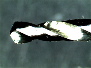 |
(1) Lighting FZ 300 PC 2 standard 80 lights LED ring lighting (2) Camera FZ 300 PC 2 standard 3 million pixel USB camera (3) Background color Black color (4) Options None * Bright portions of metal and the like are white spots, The dark parts are completely black. |
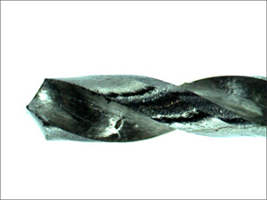
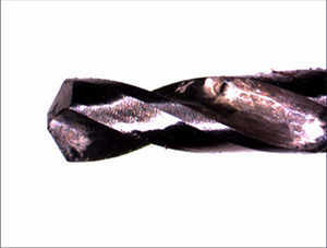
| <Example 2> | |
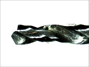 |
(1) Lighting FZ 300 PC 2 standard 80 lights LED ring lighting (2) Camera FZ 300 PC 2 standard 3 million pixel USB camera (3) Background color White Background (4) Options None
* Even if the background is white, light reflected back to the background turns around, making it easier to see from the black background. Although halation can be suppressed considerably, the part of the shadow can not be seen. |
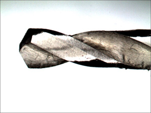
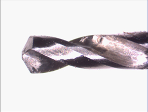
| <Example 3> | |
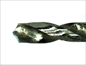 |
(1) Lighting FZ 300 PC 2 standard 80 lights LED ring lighting (2) Camera FZ 300 PC 2 standard 3 million pixel USB camera (3) Background color White V-shaped background (4) Options None
* By making the background white paper V letter, more light turns around and becomes easy to see. |
 |
|
| <Example 4> | |
 |
(1) Lighting FZ 300 PC 2 standard 80 lights LED ring lighting (2) Camera FZ 300 PC 2 standard 3 million pixel USB camera (3) Background color White (4) Options Adding polarization filters to each lens and illumination (halation removal set) |
 |
|
| <Example5> | |
 |
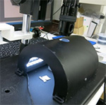
(1) Lighting Change to arch type lighting (2) Camera FZ 300 PC 2 standard 3 million pixel USB camera (3) Background color White (4) Options None
* Arched lighting is a special indirect lighting for seeing the reflecting cylinder. |
 |
|
| <Example6> | |
 |
(1) Lighting Change to arch type lighting (2) Camera FZ 300 PC 2 standard 3 million pixel USB camera (3) Background color White V-shaped background (4) Options None
※ The shadow portion and the white jump portion are gone, so you can shoot very beautifully. |
|
Another method There is an halation suppression function (average brightness function (HDR function)). (It is a function attached to the camera, there are things that are not available depending on the camera. |
|
| <Example7> | |
 |
(1) Lighting FZ 200 HD 2 standard 80 lights LED ring lighting (2) Camera FZ 200 HD 2 standard high definition camera (3) Background color White (4) Options None ※ Average brightness function OFF |
| <Example8> | |
 |
(1) Lighting FZ 200 HD 2 standard 80 lights LED ring lighting (2) Camera FZ 200 HD 2 standard high definition camera (3) Background color White (4) Options None * Brightness average function ON |
| <Example10> | |
|
Adding a white V-shaped background to the average brightness function makes it easier to see Drill’s cutting edge . |
|
 |
(1) Lighting FZ 200 HD 2 standard 80 lights LED ring lighting (2) Camera FZ 200 HD 2 standard high definition camera (3) Background color White V-shaped background (4) Options None * Brightness average function ON |
| ※C mount camera with halation suppression function (brightness average function (HDR function)) | |
 |
|
| Full HD camera with USB flash slot GR200HD2 |
|
|
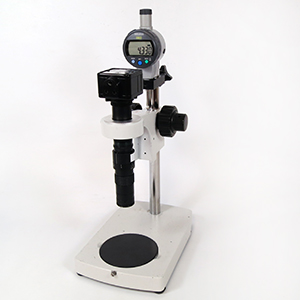
The easiest way is to combine microscope and digital indicator. Choose lens as shallow as possible in depth of field. Mechanism that moves up and down can measure accuracy with fine adjustment function with high accuracy. |
 |
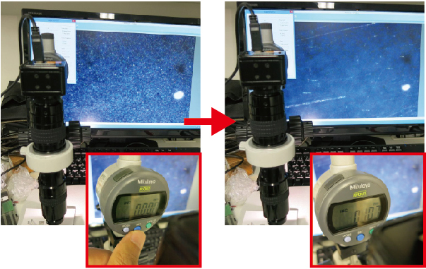
| 1.Thickness measurement | |
|
Transparency or semitransparent film is a condition under which the object that the sheet is in close contact with the substrate can be measured.
A transparent protective sheet is in close contact with the product on the right object.
Because the sheet is thin, I observed it at 600 times |
 |
|
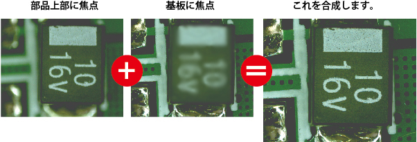
Focus on the substrate (resin) Set the value of the indicator to zero |
Focus on the top of the sheet Read the value of the indicator. This will be thick. (107 μm) |
 |
|
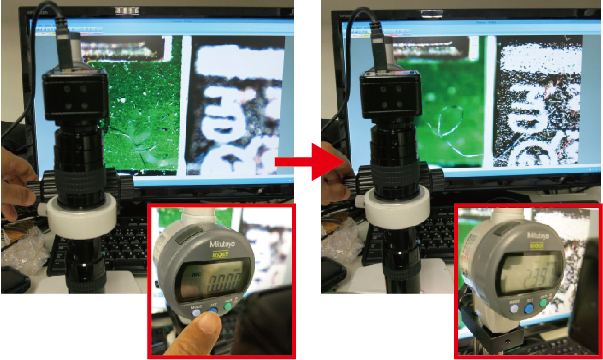
| 2.Height measurement | |
|
(1)
Measure the IC height on the left photo.
I have observed it at 200 times because I have enough height. |
 |
|
Focus on the substrate Set the value of the indicator to zero. |
Focus on the top of the IC Read the value of the indicator. This will be the height. (2.39 mm) |
 |
|
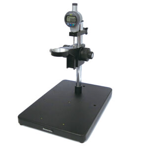
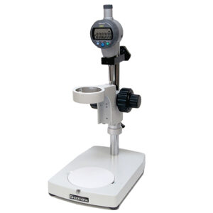
| We have two kinds of stand with digital indicator (height gauge) available. | |
  |
|
|
Coarse fine movement stand with indicator GRS-1C125XB |
Small coarse and fine stand with indicator GR-S6C125XB |
|
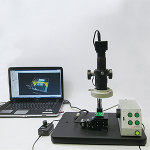
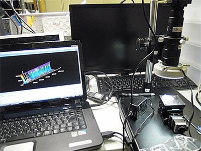
We introduce the height measurement (Z pivot measurement) system. 1. System configuration Install the Z pivot stage and the motor controller in the microscope. (Microscope (our company), Z pivot stage (Chuo Seiki products), both are general purpose goods.) |
|
 |
 |
| I will use focus synthesis software and 3D creation software of Mitani software for this system. | |
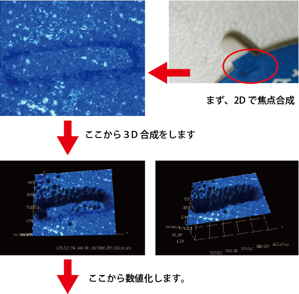
| 2.How to operate? | |
| (1)Focal Composition | |
 |
|
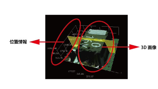
| (2)Create 3D image | |
| Combine the photos synthesized with the microscope and the position information of the motor into a 3D image. | |
 |
|
  |
|
|
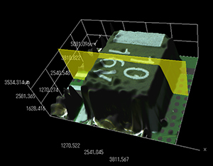
From the microscope’s perspective, the vertical surface or nearly vertical surface can not be seen. So, height measurement can be done without problems.
When there is a slope on the wall surface, a relatively beautiful 3D image can be formed.
As an example, I will make a dent of cardboard a 3D image. |
|
 |
|
|
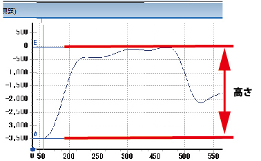
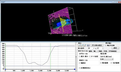
You can figure out any size and cross section shape from here. The following yellow line is a optional drawn. |
|
 |
|
 |
|
|
Since it is not a measuring machine, there is no precision. The minimum step of the Z axis table (0.5 μ this time) is the resolution. Depending on how you use it, you can get some accuracy. |
|
Select the camera that can draw a cross line on the monitor.
Our PC monitor direct camera, high vision camera has cross line display function.
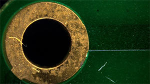
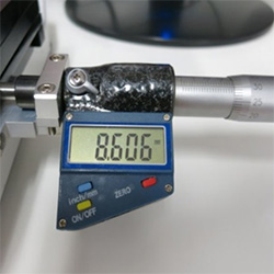
Measurement of outer diameter of rings
1. Use transillumination to emphasize edges.
2. Display the cross line on the screen.
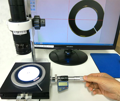
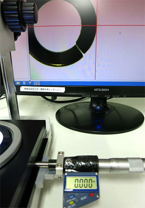
3. Align the cross line with the end of the measurement point.
4. Reset the digital micrometer to zero.
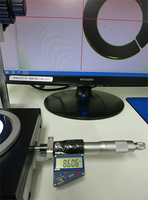
5.Using a micrometer, move to the other end side
6. At this time, the value of the micrometer will be the outside diameter.
Advantages:
(1) Calibration before measurement is unnecessary.
(2) Even objects that can not be captured on one screen can be measured.
(3) Depending on the accuracy of the micrometer, accuracy can be expressed including the calibration certificate.
Disadvantages:
(1) It takes time to measure.
(2) It can only measure horizontal and vertical.
(When using a XY table, oblique measurement is also possible)
(3)) It can measure only the distance between two points. (Measurement of angle, area, distance between centers of circles, etc. can not be done.)
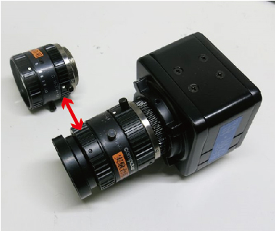
You may also remove the C mount ring when removing the lens.
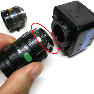
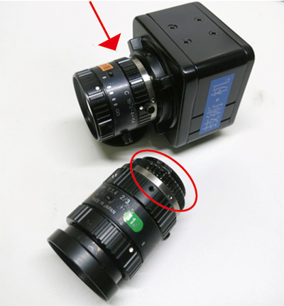
Please take a note that sufficient lens performance is not obtained in this case.
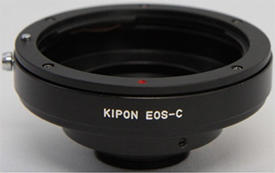
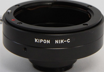
Conversion adapters as the following are on sale in order to attach the single camera lens to the C mount camera.
 |
 |
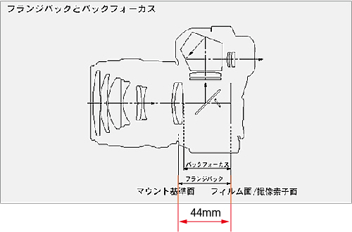
Flange back of EOS is 44mm
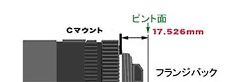
Flange back of C mount is 17.526 mm
Lenses for single lens reflex cameras can be mounted on C mount cameras.
Focus is achieved by offsetting 44 – 17 mm = 27 mm.
However, when attaching a C mount len to a single len reflex camera, the flange back is too close and there is no focus.
(If you do not let the lens into the camera, the focus will not match.)
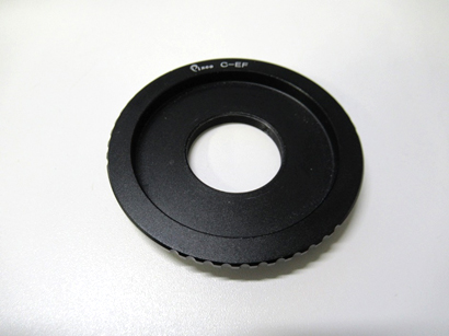
By employing this adapter, it is feasible to physically affix a C-mount lens to a single-lens reflex (SLR) camera. Nevertheless, SLR cameras typically exhibit a significantly larger sensor size compared to industrial cameras.
Consequently, the inherent incompatibility of C-mount lenses with the fundamental sensor dimensions of SLR cameras renders such a recommendation impractical.
Telecentric lens with less image distortion are superior to macro lenses when measuring high-precision dimensions.
When a telecentric lens is used, the depth of field is not extremely deep. However, there is no dimensional fluctuation of the observation image if it is within the depth of field as a feature of the telecentric lens, It is difficult to measure errors and you can measure with high accuracy.
 |
Telecentric len RT3 |
  <Distortion is large> |
High accuracy such as dimension measurement When measuring distortion, you should choose a small lens. |
 <Distortion is small> |
With a telecentric lens, distortion is small, high accuracy measurement becomes possible. |
< Shooting by telecentric lens with RT3>
 |
Glass scale in increments of 0.2 mm with a telecentric lens and shooting |
 |
<When open aperture> Focus on the area surrounded by red In the status where the aperture is open It goes to the right side of the glass scale and it is not in focus. |
 |
<When narrowing the aperture> Like the photo above, focus on the area surrounded by red. While matching, I narrowed the aperture. On the right side of the glass scale even around the broken line without blurring of images. It is clearly reflected. |
Please contact for more information.
There is resolution as lens performance.
Some expressions such as “how many lines” and “mega pixel “.
Recently, there is a tendency to place emphasis on the total representation of images including the reproducibility of contrast rather than just focusing on the resolution.
(The lens tends to degrade the reproducibility of contrast as the resolution increases.)
The resolution of the lens will change in the entire zoom range and also in the aperture.
(For example, even if it is said to be a 3M compatible lens (3 million pixel compatible lens), it is open and the resolution becomes the best condition.)
Camera resolution and lens resolution do not necessarily have to match.
If it is used for PC monitor , the resolution of monitor is lower and there are cases where you do not receive any benefit at all.
Resolution needs to be considered throughout the system.
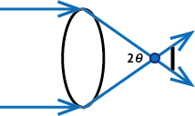
The NA (numerical aperture) of the lens is an index for judging the brightness, resolution and depth of focus of the lens.
NA = n × sin θ.
 |
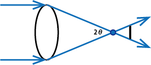 |
From above picture, 0 <θ <90 °.
It means 0 <NA <1. (In air)
(NA is determined by θ and refractive index.)
NA is larger, the lens will be brighter.
Light always tries to spread. (Diffraction)
It is necessary to narrow down at the largest possible angle in order to narrow down
NA is larger, the resolution is higher too. (When comparing at the same magnification)
The resolution = (0.61 × λ) / NA.
NA is higher, the depth of focus becomes shallower
The depth of focus = λ / (the square of NA).
Most of the microscope objective lenses have NA information.
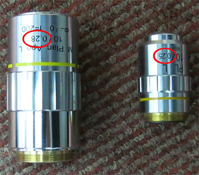
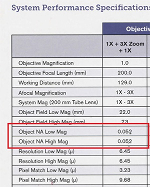
C mount zoom lens will change significantly depend on magnification.
(The lens principal point (theoretical value) will change by changing the lens magnification.)
The following is an excerpt from a catalog of a manufacturer.
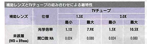
With a very special C mount zoom lens, NA does not fluctuate as shown below.
However, it becomes larger and more expensive.
The value of the aperture (iris) of the camera is shown by the F value. (It differs from lower f value.)
The value of the brightest (aperture open) status of the lens is called the open F value.
The open F value is used as an indicator of the lens brightness.
(Lens with small open F value is said to be “bright lens”.)
The brightness is halved each time, the F value becomes √ 2 times.
When the F value is 2.0 is 1, the brightness is halved F2.8 (2.0 X √ 2 = 2.8).