- What is brinell hardness
-
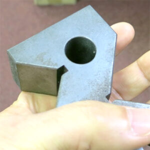
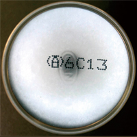
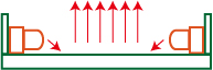
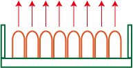
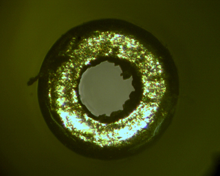
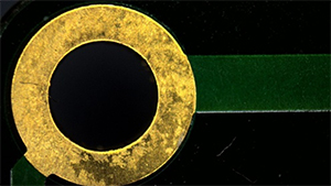
- (Brinell hardness) is a method of measuring the hardness of metallic materials by pressing a steel ball into the material under a constant load, and measuring the size of the resulting indentation.
The surface area is calculated from the diameter of the indentation, and the Brinell hardness is obtained by dividing the applied load by the surface area, denoted as HB. HB represents the load per unit area.
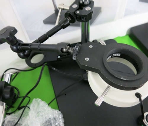
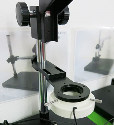
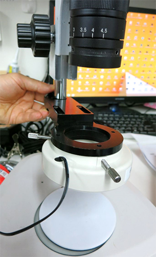
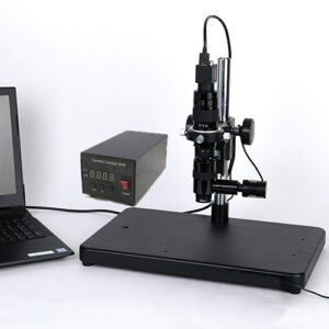
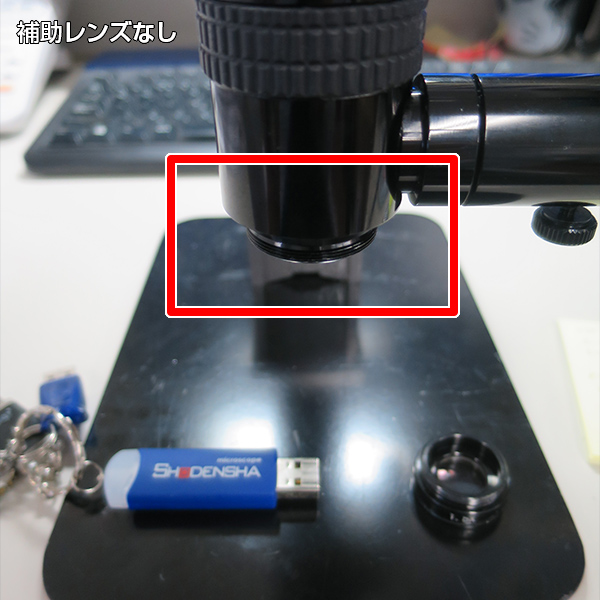
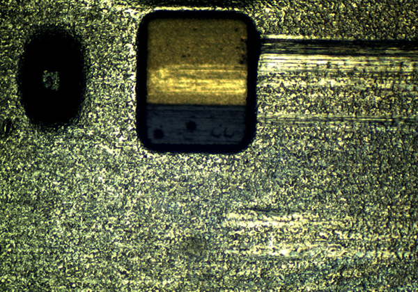
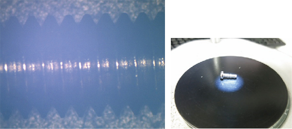
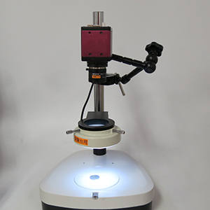
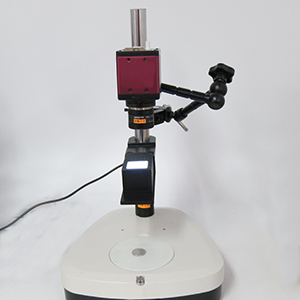
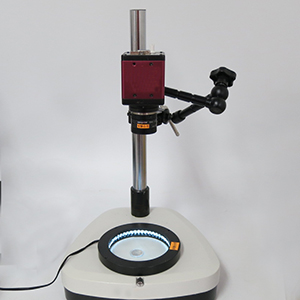
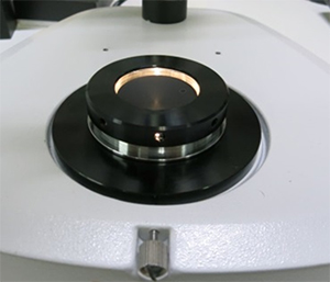
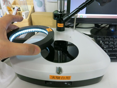
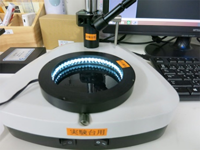
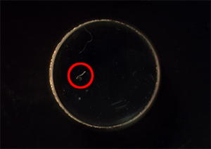
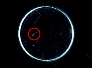
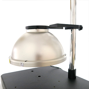
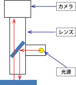
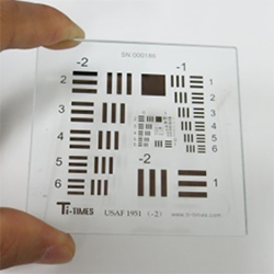
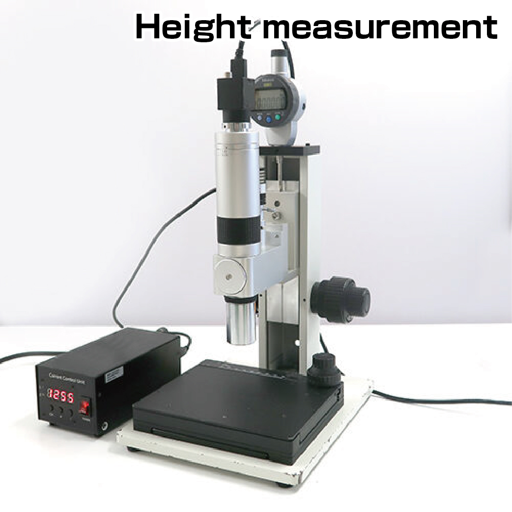
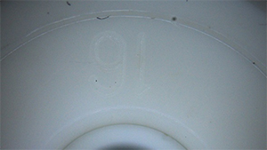
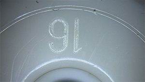
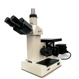
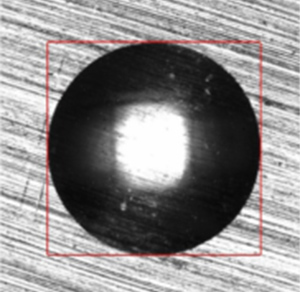
The Brinell test is conducted using a Brinell hardness testing machine, where a tungsten carbide ball is pressed into the sample, and the diameter of the indentation (Brinell impression) is measured using optical equipment.
Brinell hardness testing is widely applicable to castings, non-ferrous metals, and other materials, and is known for its high reliability.
|
Sizes of steel balls: 1, 2.5, 5, 10 mm
Testing loads: 1 kgf to 3000 kgf
Maximum hardness: 650 HB
|
 |
|
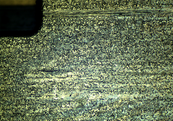
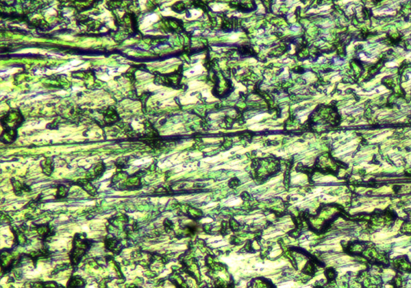
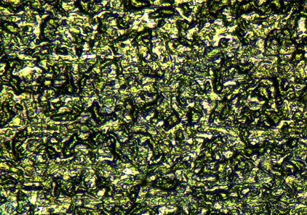
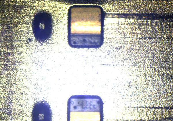
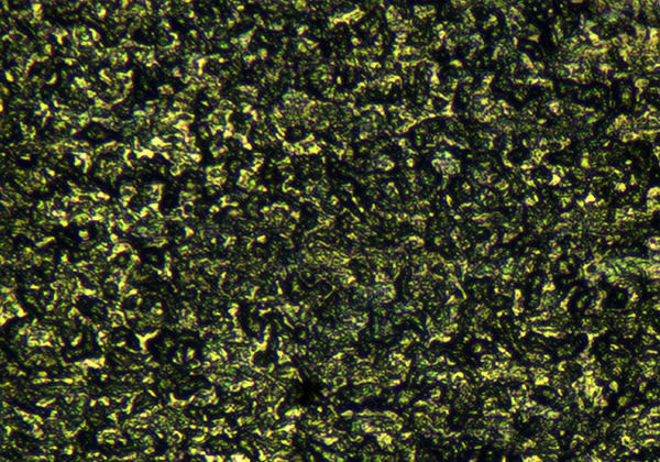
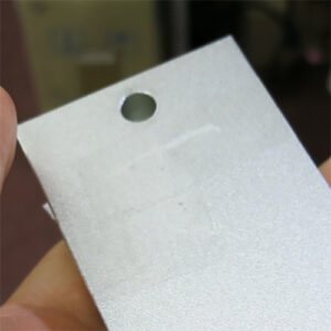
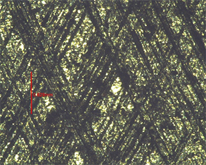
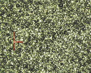
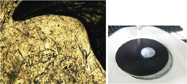
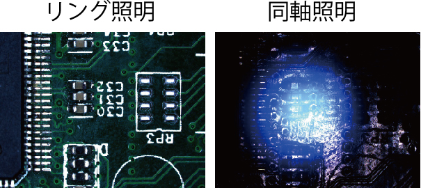
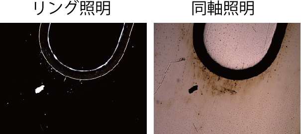
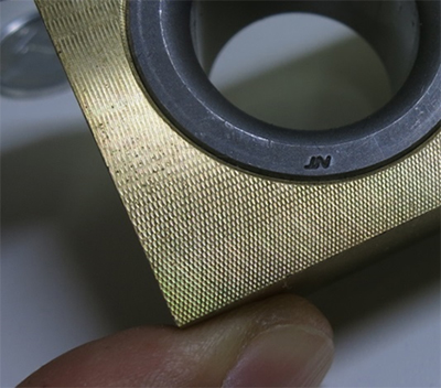
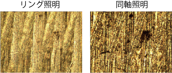
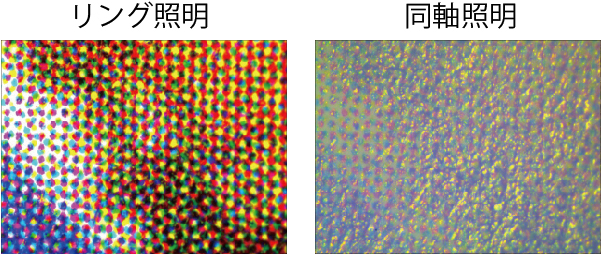
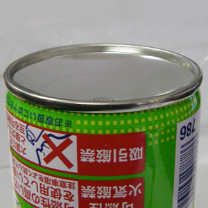
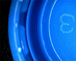
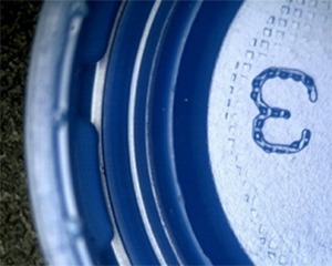
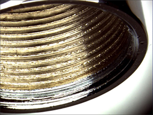
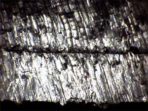
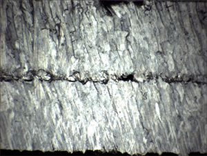
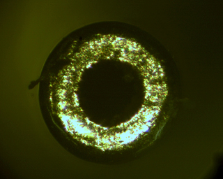
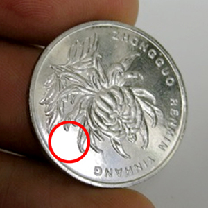
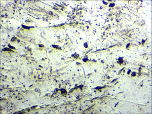
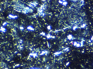
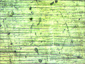
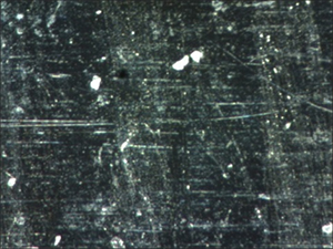
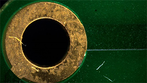
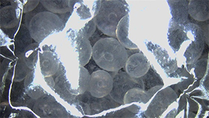
The Brinell hardness test is suitable for large samples such as castings and forgings, which have rough surfaces and heterogeneous particle structures, leaving relatively large impressions.
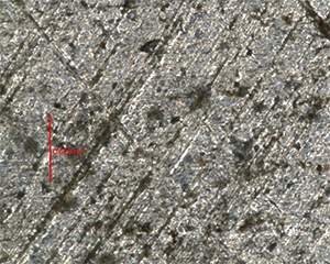
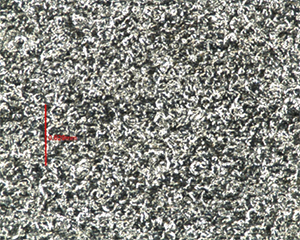
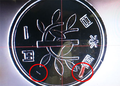
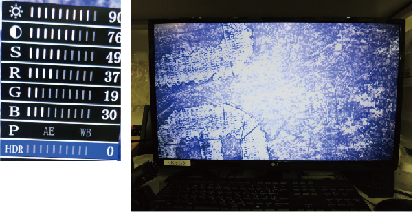
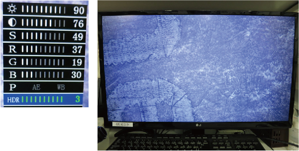
However, depending on the material, the clarity around the indentation may be unclear, leading to potential measurement errors. Moreover, the measurement process itself can be time-consuming.
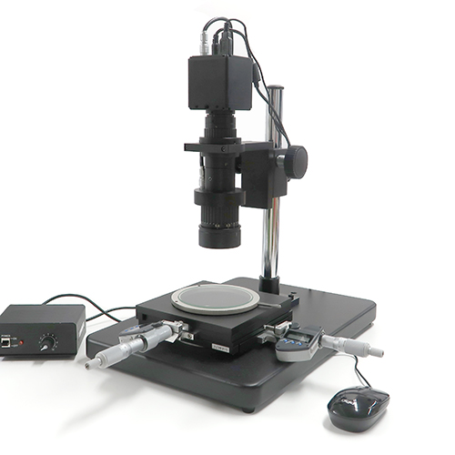
Using the following software enables fast and highly accurate Brinell hardness measurements with minimal variability.
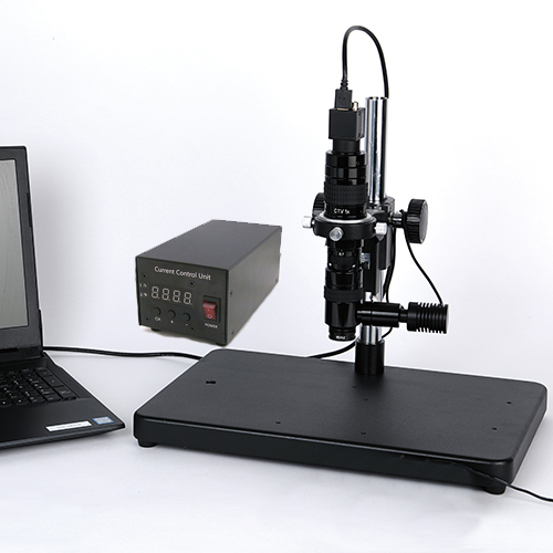
2. Introduction to efficient and high-precision Brinell hardness measurement software
 |
|
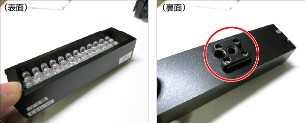
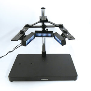
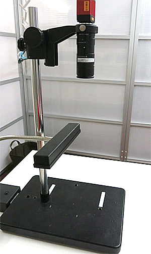
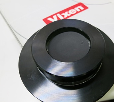
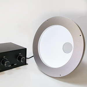
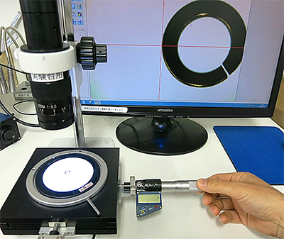
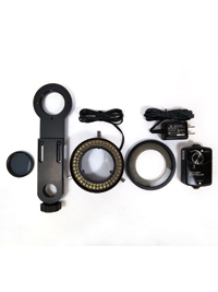
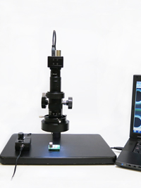
Brinell hardness testing software
(Indentation diameter reading software)
BHN MESURE
(Manufactured by Nippon Steel Technology Co., Ltd.)

|
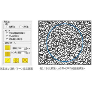
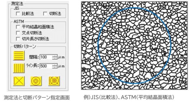
- ● Conforms to JIS and ASTM Brinell hardness test standards
・ Compliant with JIS Z 2243 and ASTM E10-08 Standard Test Method for Brinell Hardness of Metallic Materials
・ Hardness value calculation and display conform to JIS standards
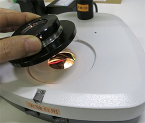
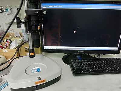
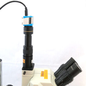
● Automatic Measurement
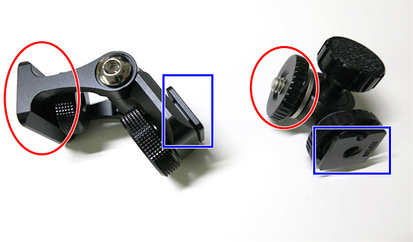
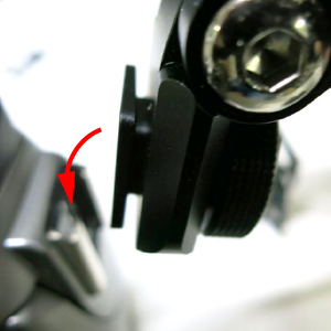
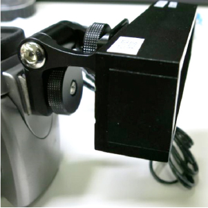
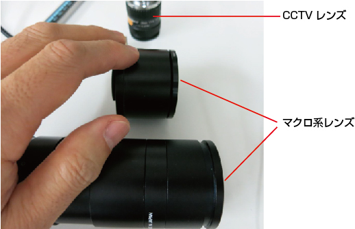
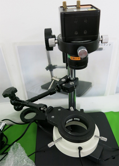
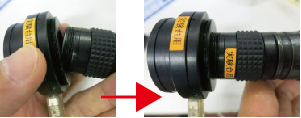
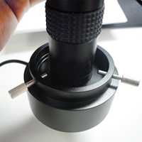
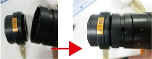
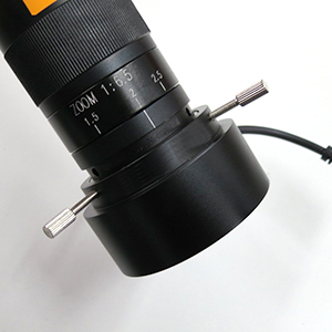
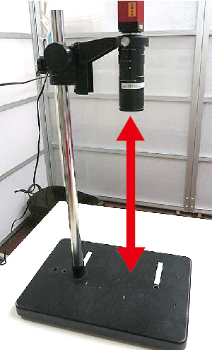
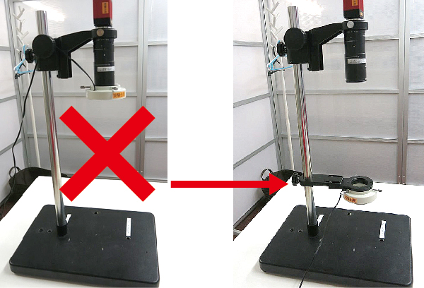
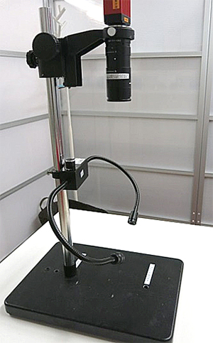
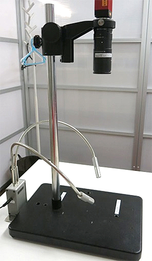
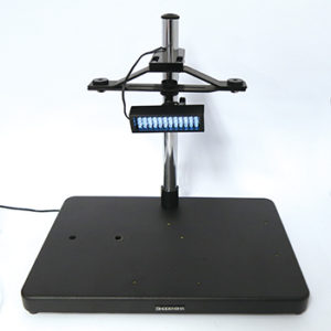
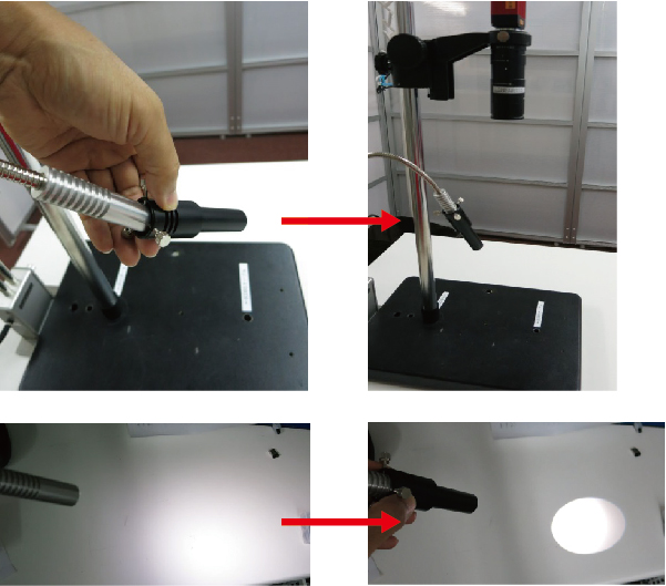
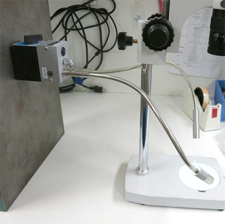
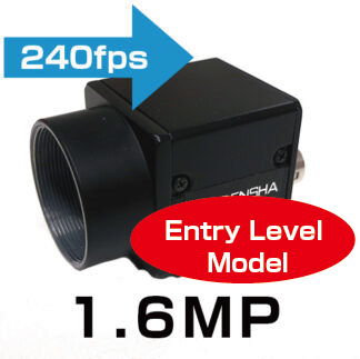
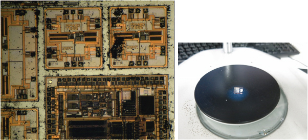
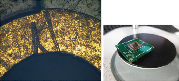
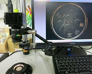
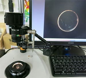
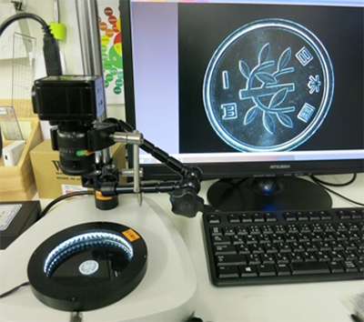
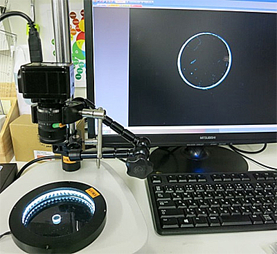
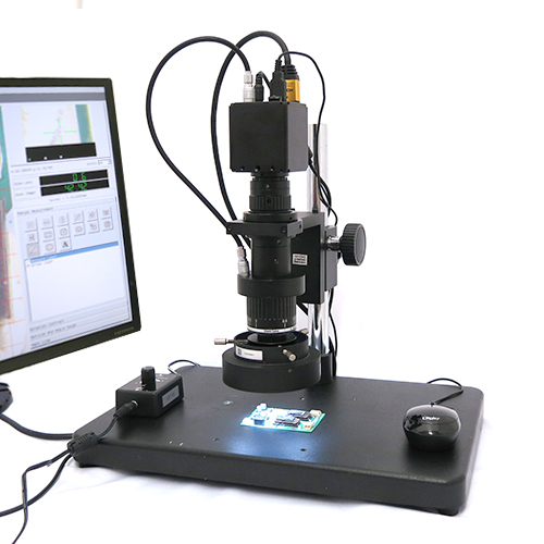
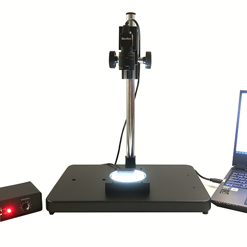
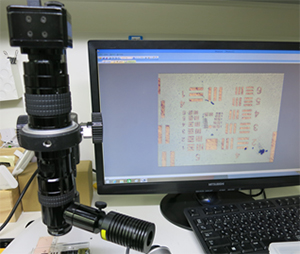
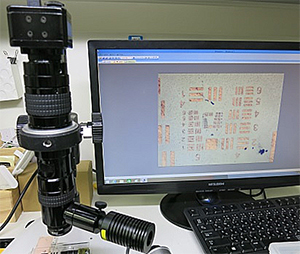
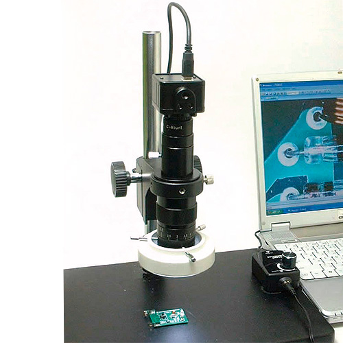
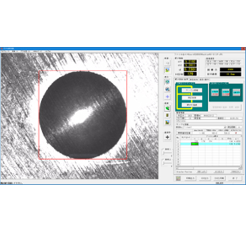
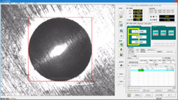
When the camera unit is set on the sample, measurement results are obtained immediately with a single action.
Automatic Brinell hardness measurement utilizes image processing technology to achieve fast and high-precision measurements according to predefined conditions.
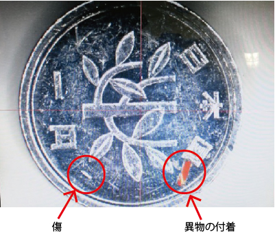
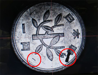
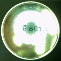
Measurement results display the measured area on the original image.
This ensures reliable verification of measurement results.
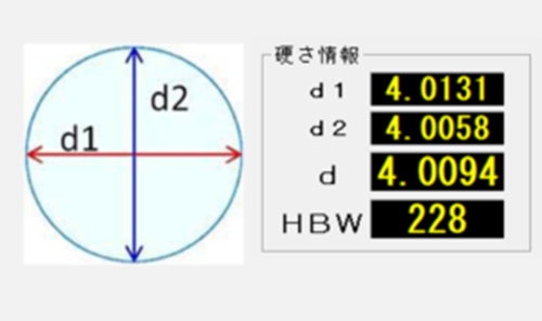
– Supports two measurement calculation methods:
・Automatic Brinell hardness measurement
・Two-point measurement
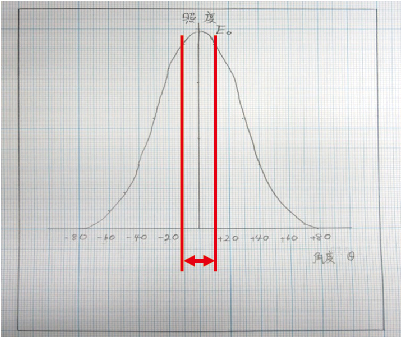
Horizontal distance d1 and perpendicular distance d2 are determined.
・
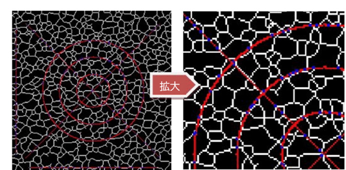
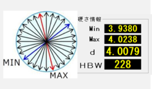
Multi-point measurement [JIS・ASTM compliant]
Calculates the minimum and maximum diameters from 3 points to 180 points (adjustable) at equal angular intervals.
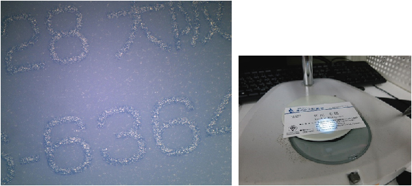
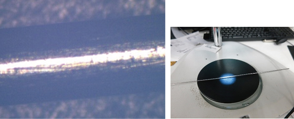
● Manual Measurement
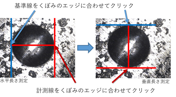
For indentations where automatic measurement is challenging or where the indentation edges are unclear, use the manual measurement tool for straightforward measurement.
・ Manual measurement (parallel lines)
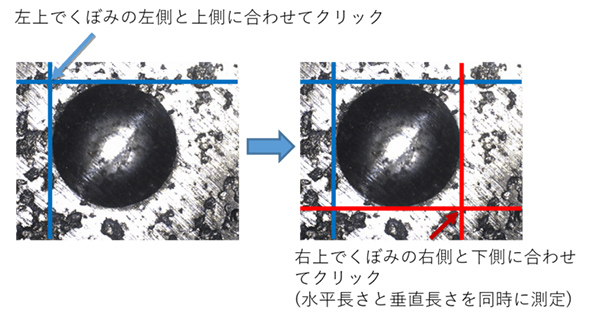
・ Manual measurement (X-Y intervals)
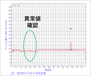
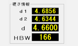
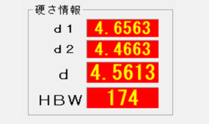
● Judgment Display
During measurement, real-time specification judgments are displayed.
 |
|
 |
| 正常値内の表示 |
|
異常値の表示(赤色表示) |
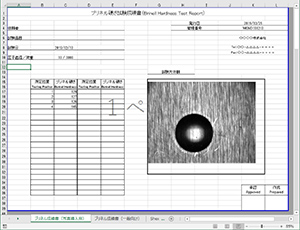
- ● Data Management
・ Measurement values and images are saved and managed by serial number, with the ability to load historical data.
・ Graph plotting and report generation can be automated.
3. Summary
We introduced software capable of Brinell hardness measurement with minimal human error and high precision and speed.
Various methods such as Brinell hardness, Vickers hardness, Rockwell hardness, Shore hardness, and Knoop hardness are used for hardness evaluation.
Each evaluation method has different inspection procedures and evaluation methods, but using the Brinell hardness obtained above, you can convert to each hardness using a “hardness conversion table.”